
LiPo Battery Thickness Tolerance and Swelling Allowance for Enclosure Design
A LiPo pouch cell that fits perfectly in a CAD drawing may become difficult to install in production or place unwanted pressure on a display, PCB, housing or internal component later in its service life. The reason is that the nominal battery thickness is only one part of the actual mechanical design envelope.
A reliable enclosure should consider beginning-of-life dimensional tolerance, battery pack construction, adhesive or foam layers, housing variation, assembly clearance and expected thickness growth during normal service. These values should come from the selected battery specification and project validation instead of relying on one universal percentage.
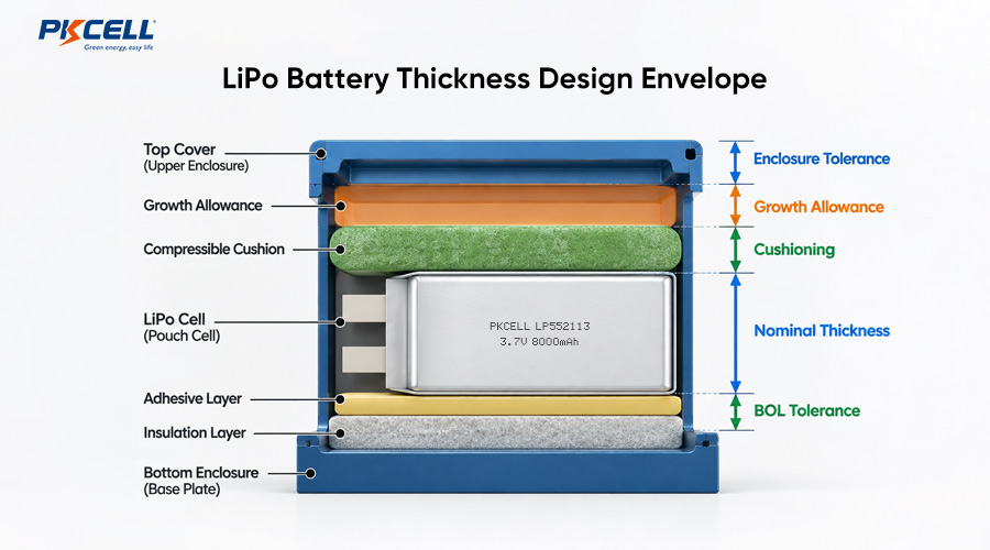
Why Nominal LiPo Thickness Is Not the Final Cavity Dimension
LiPo model numbers often provide a convenient dimensional reference. For example, the first two digits of a model such as LP603030 commonly indicate an approximate 6.0 mm cell thickness, followed by approximate width and length. However, the model number should not be treated as the final guaranteed dimension of a finished battery pack.
The completed pack may also include protection circuitry, insulation tape, labels, folded tabs, wires, connectors or localized sealing features. Depending on the construction, one of these components may define the true maximum thickness.
For additional guidance on interpreting LiPo model numbers and dimensions, see the PKCELL Lithium Polymer Battery Size Chart.
For enclosure design, engineers should request a dimensioned drawing for the exact battery configuration being purchased. The drawing should clearly define where thickness is measured and whether the maximum dimension includes the label, insulation, protection circuit, tab fold or other local high points.
Four Thickness Factors to Consider
1. Beginning-of-Life Manufacturing Tolerance
Electrode coating, stacking, electrolyte filling, pouch forming, sealing and final battery assembly introduce dimensional variation. Therefore, the maximum beginning-of-life thickness is normally more useful for enclosure design than the nominal thickness alone.
The measurement method also matters. State of charge, temperature, rest time, measuring position and applied gauge pressure can affect the measured result. For this reason, the supplier and customer should agree on a repeatable measurement condition.
2. Reversible Charge-State Expansion
A pouch cell can experience small thickness changes during normal charge and discharge. This reversible electrochemical expansion is different from abnormal gas swelling. Its magnitude depends on cell chemistry, electrode design, state of charge, temperature and operating conditions.
3. Irreversible Life-Cycle Growth
Battery thickness can gradually increase as the cell ages. Elevated temperature, long storage at high state of charge, demanding charge conditions and intensive cycling may accelerate degradation. The mechanical allowance should therefore reflect the real duty cycle and expected service life of the product.
4. Abnormal Swelling
Pronounced gas generation, rapid deformation or visibly uneven expansion should not be treated as normal enclosure tolerance. A swollen, leaking, damaged, unusually hot or abnormal-smelling battery should be isolated and handled according to an approved safety procedure.
Build the LiPo Enclosure with a Stack-Up Calculation
A useful enclosure calculation starts with the worst-case contributors in the thickness direction instead of multiplying the nominal cell thickness by a fixed percentage.
Added materials may include adhesive, insulation film, foam, labels, spacers or thermal interface materials. If a compressible pad is used, its minimum and maximum compressed thickness should be considered rather than simply adding its uncompressed thickness.
| Stack-Up Item | What to Confirm | Common Design Risk |
|---|---|---|
| Finished battery thickness | Maximum value, measurement points, SOC, temperature and measurement method | Using nominal bare-cell thickness as the final pack dimension |
| Life-cycle thickness growth | Supplier-approved limit for the intended temperature, SOC and duty cycle | Applying one universal percentage to every LiPo cell |
| Adhesive and insulation | Maximum material thickness and compression behavior | Ignoring adhesive, tape or insulation tolerance |
| Foam or cushioning | Compression range, force-deflection behavior and aging | Applying excessive pressure to the pouch cell |
| Enclosure | Molding tolerance, warpage, ribs and structural deflection | Designing only around nominal CAD dimensions |
| Assembly clearance | Battery insertion, wire routing, connector position and service access | Scraping, folding or pinching the pouch during assembly |
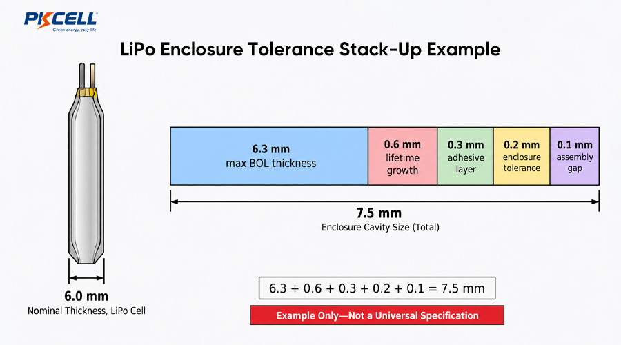
Illustrative Stack-Up Example
Assume a hypothetical battery pack has a nominal thickness of 6.0 mm. The battery supplier defines 6.3 mm as the maximum beginning-of-life thickness under an agreed measurement method.
The enclosure team then assigns 0.6 mm for validated life-cycle thickness growth, 0.3 mm for the maximum adhesive stack, 0.2 mm for inward housing tolerance and 0.1 mm for assembly clearance.
Minimum cavity thickness = 6.3 + 0.6 + 0.3 + 0.2 + 0.1 = 7.5 mm
This calculation is only an example of the design method. The 7.5 mm result should not be reused for another battery without validating the actual cell, pack structure and application conditions.
Is a Fixed 10% Swelling Allowance Enough?
A percentage such as 5% or 10% can sometimes be useful during very early concept development, but it should not automatically become the released enclosure specification. Different pouch cells can behave differently depending on electrode design, chemistry, thickness, temperature, state of charge and intended service life.
This is especially important for thin cells. A relatively small absolute thickness increase can represent a large percentage of the original cell thickness, while localized features such as a protection circuit, label or tab fold may still control the maximum envelope.
The correct allowance is the one supported by the selected cell, finished pack construction, expected duty cycle, temperature range, service-life target and agreed measurement method.
The enclosure should therefore be reviewed together with the actual battery supplier before tooling is finalized.
Mechanical Design Practices for LiPo Pouch Cells
Avoid Sharp Edges and Point Loads
The aluminum-laminate pouch provides less mechanical protection than a rigid cylindrical cell can. Screw bosses, solder joints, sharp ribs, metal edges, PCB component leads and enclosure hooks should not press directly against the pouch surface.
Use smooth support surfaces and suitable electrical insulation where the battery is positioned close to a PCB or metallic component.
Protect the Seal and Tab Area
The pouch seal and tab area should not be folded, clamped or loaded unless the approved battery drawing specifically permits it. Provide a defined wire route and suitable bend radius, and make sure connectors cannot press into the battery surface.
Width and length clearance should also account for seal variation, tab geometry, wiring and assembly access rather than only the active electrode area.
Use Foam as an Engineered Component
Soft foam can help control movement, compensate for dimensional variation and improve vibration resistance. However, foam should not be selected by thickness alone.
Important properties include compression force, usable compression range, compression set, temperature performance, aging behavior and compatibility with the pouch material.
Do not use a rigid lid, strong spring or dense foam to force a pouch cell into a fixed thickness unless the cell supplier has approved the compression requirement.
Consider More Than the Z-Axis
Thickness is often the tightest dimension in portable electronics, but width and length also require tolerance. Pouch edges, folded seals, wire exits and protection boards can extend beyond the active cell body.
For small electronic products, a battery that fits in the Z-axis but is tightly constrained in X or Y may still experience unwanted mechanical loading.
PKCELL provides multiple Li-Polymer battery sizes for OEM applications. Where an existing model cannot meet the required envelope, the battery size, connector, wire length, protection circuit and other pack details can be evaluated as part of a custom battery pack project.
Prototype Validation Before Enclosure Tooling
Mechanical validation should begin before enclosure tooling is frozen. CAD clearance alone cannot verify whether the battery remains suitable throughout manufacturing variation and service life.
- Define the battery measurement condition, including SOC, temperature, rest time, gauge position and applied measuring force.
- Measure the complete finished pack rather than only the bare pouch cell.
- Evaluate multiple samples and production lots instead of relying on one engineering sample.
- Check the battery cavity at maximum material condition.
- Cycle and store representative packs under the intended electrical and thermal conditions.
- Measure thickness growth at defined intervals.
- Confirm that the battery can be inserted without scraping, folding, squeezing or damaging the pouch.
- Verify that the PCB, display, housing and other components do not become load-bearing surfaces for the battery.
Where the battery is used in portable electronics, wearable equipment, IoT devices or other compact systems, early mechanical review can reduce enclosure revisions later in development. PKCELL’s consumer electronics battery solutions include battery selection and custom pack development for space-constrained products.
Information to Send Your Battery Supplier
Providing complete project information allows the battery supplier to evaluate mechanical and electrical requirements together.
- Available battery cavity length, width and thickness
- Enclosure drawing or CAD dimensions
- Required voltage and capacity
- Continuous and peak discharge current
- Charging conditions
- Operating and storage temperature range
- Expected cycle life and calendar life
- Required connector and wire length
- Wire exit direction
- Protection circuit or NTC requirements
- Foam, adhesive or mounting concept
- Certification and target sales markets
- Estimated annual demand
For a project-specific evaluation, you can send these requirements through the PKCELL contact page.
Common LiPo Enclosure Design Mistakes
- Using the LiPo model number as an exact finished-pack dimension.
- Designing the enclosure around nominal thickness rather than maximum thickness.
- Applying a fixed swelling percentage without supplier-specific data.
- Ignoring tape, labels, protection boards, foam and adhesive thickness.
- Allowing screws, PCB components or enclosure ribs to contact the pouch.
- Using enclosure closure force to compress the battery.
- Ignoring the wire exit and connector in the mechanical envelope.
- Testing only one new battery at room temperature.
- Confusing expected life-cycle growth with abnormal swelling.
- Finalizing injection-mold tooling before battery fit validation.
Frequently Asked Questions
How much thickness clearance should be left for a LiPo battery?
There is no universal value. The cavity should be calculated using the maximum finished-pack thickness, validated life-cycle growth, adhesive or cushioning materials, enclosure tolerance and required assembly clearance.
Does LP603030 mean the battery is exactly 6.0 mm thick?
No. It normally indicates an approximate nominal thickness of 6.0 mm. The released cell or pack drawing should be used to determine the actual dimensional tolerance and maximum finished thickness.
Is some LiPo thickness growth normal?
Small reversible dimensional changes during charge and gradual bounded growth during aging can occur. Rapid, uneven or excessive swelling should be treated as an abnormal condition and investigated.
Can foam be placed above a LiPo battery?
Yes, if the foam is selected for controlled cushioning rather than excessive compression. Its thickness, force-deflection curve, compression set, aging and temperature behavior should be evaluated.
Should the battery touch the enclosure lid?
The battery should not rely on an uncontrolled rigid lid force to restrain expansion. Any intentional compression should be specified and validated with the battery supplier.
When should the battery supplier review the enclosure design?
Ideally before industrial design and tooling are finalized. Early review allows the cell body, pouch seal, protection circuit, wires, connector, cushioning and service-life thickness allowance to be considered together.
Conclusion
Successful LiPo enclosure design starts with a verified maximum pack dimension rather than a nominal model code. Manufacturing tolerance, normal charge-state expansion, service-life thickness growth, adhesive, cushioning and housing tolerances should be considered separately and then combined into a mechanical stack-up.
The enclosure should protect the pouch from sharp objects, point loads and uncontrolled compression while providing enough space for the validated battery envelope. Prototype fit checks and life-cycle testing should be completed before the housing design is frozen.
Need a LiPo Battery for a Space-Constrained Product?
Send PKCELL your available battery dimensions, required voltage and capacity, load profile, operating temperature, connector, wire length and target service life. The engineering team can evaluate a standard LiPo model or a customized battery configuration for your enclosure.
Post time: Oct-08-2026


