
Cordless Vacuum Cleaner Battery Pack Design: Cell Selection, Peak Current, Heat and Runtime
A cordless vacuum battery must start a demanding motor, sustain high-power cleaning modes and provide useful runtime inside a compact enclosure. Choosing a cell by capacity alone can lead to voltage sag, BMS shutdown, excessive heat or disappointing cleaning time. Successful cordless vacuum battery pack design begins with the real load profile and treats the cells, conductors, protection circuit, connector and enclosure as one system.
Why Vacuum Cleaner Battery Packs Are Difficult to Design
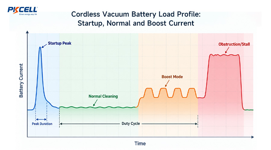
Cordless vacuum cleaners combine a motor-driven load with strict limits on battery size, weight and temperature. Their current demand also changes during use. Starting the motor, switching into turbo mode, restricting airflow or obstructing a powered brush can each create a different electrical condition.
A useful load profile should distinguish:
- Startup current: the short transient required to accelerate the motor.
- Normal cleaning current: the sustained load during routine operation.
- Boost-mode current: the higher load used for maximum suction.
- Peak duration and repetition: how long a peak lasts and how often it occurs.
- Low-SOC current: the load near the end of the discharge cycle.
- Stall or obstruction current: an abnormal but credible condition requiring coordinated protection.
Start With a Measured Motor Load Profile
Measure voltage and current at the battery terminals with equipment fast enough to capture short transients. A motor nameplate, adapter rating or slow multimeter may not show the event that causes the battery voltage to collapse or the BMS to trip.
Record the following information for each operating mode:
- average and maximum sustained current;
- startup or inrush current;
- peak-current duration and repetition rate;
- boost-mode duty cycle;
- pack voltage during the peak;
- motor-controller efficiency;
- device shutdown voltage; and
- ambient and internal battery temperatures.
If the motor controller behaves approximately like a constant-power load, battery current can rise as pack voltage falls:
Use this equation only for preliminary screening. The final design should use measurements from the actual motor, controller, filter, brush head and airflow path.
Cell Selection: Capacity Is Only One Requirement
Cell capacity indicates stored charge, but it does not prove that the cell can supply a vacuum motor. Engineers must also examine continuous discharge current, defined pulse capability, internal resistance, voltage sag, temperature limits, cycle-life conditions and mechanical dimensions.
Begin with the exact model specification rather than assuming that all cells with the same format or capacity perform alike. PKCELL’s guide to
reading a lithium-ion cell datasheet
explains how minimum capacity, discharge conditions and cutoff voltage influence an OEM design.
18650 vs. 21700 Cells for Vacuum Cleaner Packs
| Design factor | 18650 cells | 21700 cells | Engineering question |
|---|---|---|---|
| Pack layout | Smaller diameter can provide flexible arrangement options. | Larger format may achieve the energy target with fewer cells. | Which format fits the enclosure after adding holders, BMS and insulation? |
| Capacity | Available in many energy-oriented and high-rate models. | Can provide higher capacity per cell, depending on the model. | What is the minimum usable energy under the real load? |
| Power capability | High-drain models are available. | High-rate options are available for demanding motor loads. | Can the exact model support repeated peaks without excessive sag or heat? |
| Connections | A target energy level may require more cells and welds. | Some designs can use fewer cells and connections. | How do cell count and interconnect layout affect resistance and production? |
| Weight and size | Smaller individual cell, but the complete pack may use more cells. | Larger individual cell, potentially with a lower total cell count. | Which finished pack meets the product’s weight and balance target? |
Featured High-Rate 21700 Cell for Vacuum Projects
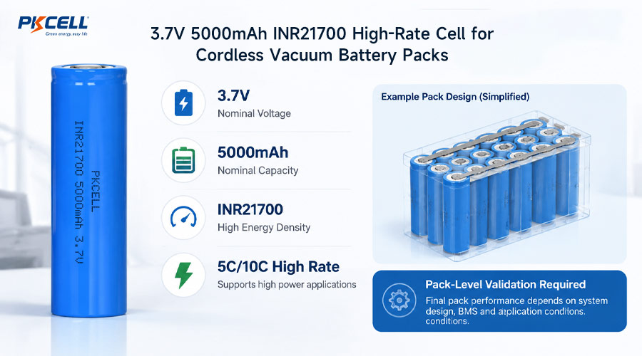
For vacuum platforms requiring both energy capacity and high-rate performance, engineers can evaluate the
3.7V 5000mAh INR21700 5/10C High Rate Li-ion Battery
.
Its 21700 format and 5000mAh capacity make it a relevant candidate for motor-driven applications. However, the 5C/10C designation must be interpreted using the exact product specification, including whether the value is continuous or pulsed and what duration, temperature, cutoff voltage and cooling conditions apply.
The suitability of this cell for a particular vacuum cleaner must be confirmed against the measured load profile and the thermal behavior of the assembled pack. The cell rating does not automatically become the output rating of the finished battery.
Calculate Peak Current at Cell Level
Cells connected in series raise the pack voltage. Cells connected in parallel increase pack capacity and share the load current. For an initial calculation:
For example, a 30A pack load in a 2P configuration ideally places 15A on each cell. Real current sharing is not perfectly equal. Differences in cell resistance, temperature, weld quality and conductor geometry can cause one parallel branch to carry more current.
Peak capability should never be represented by current alone. A useful specification includes peak duration, repetition, rest time, starting state of charge, ambient temperature, allowable voltage sag and the maximum permitted cell temperature.
A cell that survives one short current pulse may not tolerate the same pulse repeated throughout a cleaning cycle inside a warm enclosure.
For additional context, see PKCELL’s comparison of
low-drain and high-drain lithium-ion cells
.
The Complete Current Path Must Support the Load
Pack output can be limited by any component between the cells and the motor controller. A high-rate cell cannot correct an undersized conductor, high-resistance weld, warm connector or unsuitable BMS.
- Cells and parallel groups
- Cell tabs and welds
- Nickel strips, copper busbars or hybrid conductors
- Fuse and protection devices
- BMS MOSFETs and PCB copper
- Wires and terminals
- Pack connector and device-side mating connector
Voltage drop = Current × Total resistance
Resistive heat = Current² × Total resistance
Because current is squared in the heating equation, doubling current creates approximately four times the resistive heat when resistance remains unchanged. This is one reason boost mode can have a much greater thermal impact than its operating time suggests.
PKCELL’s guide to
nickel strip versus copper busbars
explains how conductor material, dimensions, path length, weld quality and cooling affect high-current battery packs.
Match the BMS to Continuous, Peak and Fault Current
A single printed BMS current rating is not enough for a vacuum battery specification. The BMS should distinguish between:
- Continuous current: the sustained load the board can carry within its validated thermal conditions.
- Temporary peak current: the permitted current for a stated duration and duty cycle.
- Overcurrent threshold: the current at which the protection circuit begins its shutdown sequence.
- Detection delay: how long the abnormal current can remain before the MOSFETs switch off.
- Short-circuit protection: the response to a severe high-current fault.
- Charge-current rating: which may differ from the discharge-current limit.
Normal startup must pass without nuisance shutdown, while an obstructed brush or genuine fault should be interrupted before the cells, conductors or connector exceed their qualified limits. Protection settings must therefore be coordinated with both the load profile and the hardware.
Heat Management and NTC Placement
Heat can originate in the cells, welds, conductors, connector and BMS power stage. The enclosure then determines how quickly that heat can escape. Dust, restricted airflow and closely packed components can make the actual vacuum environment more demanding than an open-bench cell test.
Practical thermal design measures
- Use balanced conductor paths to improve current sharing.
- Avoid placing the BMS power stage against the hottest cell group.
- Provide appropriate spacing and controlled heat-transfer paths.
- Measure weld, busbar, BMS and connector temperatures—not only cell temperature.
- Test repeated boost-mode cycles with realistic cooling intervals.
- Validate at high ambient temperature and low state of charge.
- Repeat critical tests using aged or higher-resistance cells.
An NTC sensor measures its installed location rather than the entire pack. Its position and response time should represent the limiting cell or component. Review
NTC thermistor placement in lithium battery packs
when defining sensor locations and shutdown thresholds.
Calculate Realistic Cordless Vacuum Runtime
Start with nominal pack energy:
For a basic constant-load estimate:
Nominal energy is not equal to energy delivered to the motor. Voltage sag, device cutoff, controller losses, high discharge rate, temperature, capacity tolerance, BMS consumption and aging all reduce usable energy.
A vacuum cleaner with multiple operating modes should use a weighted duty-cycle calculation:
As an illustrative calculation, a test cycle using 80W for 70% of the time and 200W for 30% of the time has a weighted average of 116W before other system losses are included. The runtime estimate should then use measured usable pack energy under similar conditions.
Define both beginning-of-life and end-of-life runtime. The test specification should also identify the cleaning mode, brush head, filter condition, ambient temperature, cutoff voltage and rest periods.
Common Design Mistakes
- Choosing the highest mAh rating: capacity alone does not establish motor-current capability.
- Using a pulse rating as continuous current: undefined peak values cannot support thermal design.
- Ignoring low-SOC operation: voltage sag and battery current can become more demanding near cutoff.
- Assuming equal current sharing: parallel cells and connections have resistance variation.
- Sizing only the cells: the BMS, welds, conductors and connector may become the real limit.
- Testing only at room temperature: cold starts and hot enclosures can expose different problems.
- Quoting runtime without conditions: cleaning mode, airflow, attachments and aging affect the result.
- Changing the cell without revalidation: cells with similar dimensions and capacity can have different resistance and thermal behavior.
Prototype Validation Checklist
- Measure startup, continuous, boost and obstruction-related current.
- Record pack and series-group voltage during the highest load.
- Confirm BMS peak-current timing and protection response.
- Measure voltage drop across the BMS, conductors and connector.
- Map cell, weld, BMS, wire and connector temperatures.
- Test at full, medium and low state of charge.
- Test at the product’s limiting ambient temperatures.
- Run repeated cleaning and boost-mode cycles.
- Verify runtime with the actual motor, controller, filter and attachments.
- Confirm vibration, drop, connector retention and enclosure requirements.
- Review charger compatibility and the full series-cell voltage.
- Confirm transport and target-market requirements for the final production configuration.
Request a Custom Cordless Vacuum Battery Solution
Send PKCELL your voltage window, measured continuous and peak current, pulse duration, runtime target, maximum dimensions, weight limit, temperature range, charger, connector, annual quantity and destination markets.
PKCELL can review the 3.7V 5000mAh INR21700 high-rate cell, series-parallel configuration, BMS, NTC placement, current path, enclosure integration and prototype requirements for your vacuum cleaner project.
Frequently Asked Questions
Is a 5000mAh 21700 cell suitable for a cordless vacuum cleaner?
It can be a suitable candidate if its verified continuous current, defined pulse performance, voltage sag and thermal behavior meet the vacuum’s load profile. The complete pack must also have an appropriate parallel count, BMS, conductors, connector and cooling design.
What does 5C or 10C mean for a 5000mAh cell?
C-rate relates current to capacity, so 1C for a 5Ah cell corresponds mathematically to 5A. However, a 5C or 10C designation must be checked against the exact specification to determine whether it is continuous or pulsed and what time, temperature and cutoff conditions apply.
Why does a cordless vacuum stop in turbo mode?
Possible causes include cell voltage sag, an undersized BMS, overcurrent protection, excessive BMS temperature, a high-resistance connection, low state of charge or aged cells with increased resistance.
Do more parallel cells increase runtime?
Parallel cells increase nominal capacity and can share load current, but they also add weight, volume, connections and fault energy. Current sharing and thermal behavior must be verified in the finished pack.
What information should an OEM include in a vacuum battery inquiry?
Include nominal and full-charge voltage, continuous and peak current, peak duration, boost-mode duty cycle, runtime target, dimensions, weight, operating temperature, charger, connector, expected quantity and required markets. Submit these details through the
PKCELL battery inquiry page.
Conclusion
Cordless vacuum battery pack design requires a balance of energy, power, heat, protection and mechanical integration. The 3.7V 5000mAh INR21700 high-rate cell is a relevant option to evaluate, but its suitability depends on the actual motor load, pack configuration and operating environment.
Begin with measured current data, design every component in the current path for the intended load and verify the production-intent pack under realistic cleaning conditions. To discuss cell selection, BMS settings, enclosure constraints and samples, explore PKCELL’s
custom battery pack engineering service
or submit your project requirements for review.
Post time: Sep-22-2026


