
21700 Battery Pack Design for Portable Test Equipment
Portable test equipment asks more of a battery than long runtime. A field oscilloscope, data logger, calibrator, cable tester or portable analyzer may combine sensitive analog measurement circuits with processors, displays, communications, sensor excitation and high-speed data storage. These loads do not operate continuously or draw current in the same way.
A suitable 21700 battery pack must support those changing loads without creating measurement interference, unexpected shutdowns or excessive thermal drift. It must also remain practical to charge, transport, service and manufacture in volume.
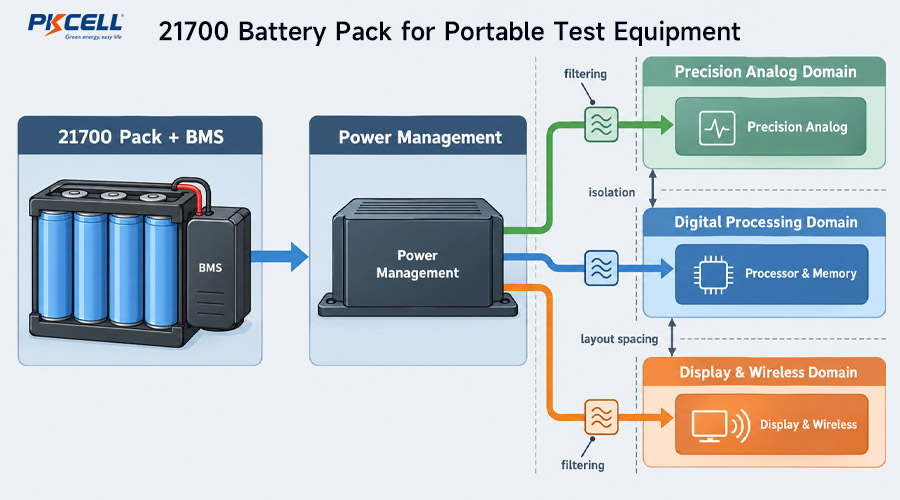
Why Portable Test Equipment Is a Special Battery Application
A conventional portable product may tolerate brief voltage variation as long as it keeps running. Test equipment may have stricter requirements because its job is to detect, generate or record small electrical changes. Battery behavior can affect measurement performance indirectly through the power architecture.
Typical subsystems include:
- High-resolution analog-to-digital or digital-to-analog converters
- Low-noise analog front ends and precision voltage references
- Isolated input, output or communication channels
- Processors, FPGAs and memory with fast-changing current demand
- Displays and backlights with adjustable power consumption
- Wi-Fi, Bluetooth, cellular or other communication modules
- Sensor excitation, loop power or programmable test outputs
- Fans, pumps, printers, relays or other intermittent loads
The battery pack does not need to be a precision reference, but it must not undermine the instrument’s precision power domains.
The 21700 format can be attractive because its larger cylindrical body can hold more energy per cell than many 18650 alternatives. However, capacity, allowable current and temperature behavior vary by model. Review the PKCELL 21700 battery guide before screening exact cell candidates.
Map Every Operating Mode Before Selecting the Pack
Average current alone is not enough for a portable instrument. Create a timed power profile covering the complete field workflow.
| Equipment Mode | Likely Battery Impact | What to Measure |
|---|---|---|
| Power-up and self-test | Processor, FPGA, display and internal rails may start together. | Peak current, pulse duration, voltage sag and startup success. |
| Idle or standby | Low current may continue for long periods between measurements. | Standby power, sleep current, wake interval and shutdown current. |
| Active measurement | Analog circuits, processor and acquisition memory operate together. | Current, noise spectrum, sample rate and measurement uncertainty. |
| Sensor or device excitation | The instrument may supply power to an external sensor or loop. | Maximum output current, overload duration and conversion efficiency. |
| Wireless upload | Radio transmission can add repetitive current pulses. | Pulse amplitude, repetition rate and effect on sensitive channels. |
| Data processing or storage | Computing and memory activity can create fast load transitions. | Transient current, rail stability and recording integrity. |
| Charging while operating | Charger and adapter noise may couple into measurements. | Measurement performance, leakage paths, heat and charge time. |
| Low-battery operation | Constant-power converters can draw more current as voltage falls. | Maximum current, warning accuracy, voltage sag and shutdown behavior. |
Measure these modes on representative hardware whenever possible. If the final electronics are not available, use conservative load profiles and update the pack requirements when prototype data becomes available.
Choose the 21700 Series and Parallel Configuration
Cells connected in series raise pack voltage. Parallel cells increase capacity and share load current. The correct architecture depends on the instrument’s conversion stages, peak load, runtime target and available enclosure.
A 1S design can simplify the battery but may require high step-up ratios for analog, display or excitation rails. A multi-series design can reduce current for a given power level, but it adds cell-group monitoring and requires a charger matched to the full series configuration.
Do not choose the voltage solely to avoid one converter stage. Consider conversion efficiency, noise, required isolation, creepage and clearance, component ratings, charger availability and behavior from full charge to the lowest permitted pack voltage.
Calculate Runtime from Usable Energy
Datasheet capacity is normally measured under defined conditions. Field equipment may operate at higher load, lower temperature or a higher system cutoff. Some of the nominal energy can remain unavailable when the instrument shuts down.
For a changing load, calculate energy consumed during each operating mode:
Include conversion loss, display brightness, radio transmission, sensor power, standby consumption, low-temperature performance and an operational reserve. Repeat the calculation for an aged pack if the product guarantees runtime near the end of its service life.
Avoid sizing from the advertised milliamp-hour value alone. The selected cell must also support the load without excessive sag or temperature rise.
Protect Measurement Accuracy from Power-System Noise
A rechargeable cell supplies DC energy, but the complete battery system contains switching elements. The BMS, charger, buck or boost converters, display driver and digital processor can generate conducted or radiated interference.
Separate Sensitive and Noisy Power Domains
Identify which circuits require the cleanest supply. Precision references, low-level sensor inputs and analog front ends may need different filtering or regulation from the processor, backlight and radio.
- Keep high-current switching loops physically compact.
- Route sensitive signals away from BMS switching and high-current paths.
- Avoid sharing uncontrolled impedance between analog and pulsed loads.
- Place input and output capacitors according to the converter design.
- Control cable routing, shielding and enclosure bonding at system level.
- Check switching frequencies and harmonics against measurement bands.
There is no universal grounding or filtering layout that suits every instrument. The correct approach depends on input isolation, frequency range, enclosure, converter topology and applicable safety requirements.
Test the Worst Noise-Producing Combinations
A quiet bench test with a full battery may miss field problems. Measure instrument performance with:
- Minimum and maximum pack voltage
- Display brightness at its highest setting
- Wireless transmission active
- External sensor or loop power enabled
- Data logging and storage activity
- Charging connected, if operation while charging is permitted
- Repeated processor, relay or output-load transitions
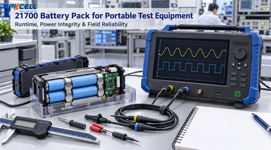
Coordinate the BMS with Transient Loads
Portable instruments can produce short current peaks during boot, wireless transmission, relay operation or output excitation. The BMS must carry valid operating pulses without nuisance shutdown while still responding correctly to real overloads and faults.
Define at least four separate current cases:
- Maximum continuous operating current
- Repetitive pulse current with duration and duty cycle
- Startup or inrush current
- Credible short-circuit or fault current
Protection thresholds should not be increased merely to hide an unexplained shutdown. Review the cell, wiring, connector, conductor, MOSFETs, fuse, converter input capacitance and thermal conditions as a complete current path.
PKCELL’s guide to defining custom battery pack safety margins explains how normal operating boundaries should remain separated from protection thresholds and qualified component limits.
Manage Heat to Protect Cells and Measurement Stability
Battery heat is not only a cell-life issue. Temperature changes near precision references, oscillators, amplifiers and analog converters can alter instrument behavior. Charging can also add heat while the device is performing a measurement.
Place the pack and BMS away from the most temperature-sensitive measurement circuits where practical. Avoid trapping battery heat against reference devices or calibration components. Thermal design should consider:
- Continuous operation at maximum ambient temperature
- Charging with the instrument on and off
- High display brightness and radio transmission
- External sensor or output power at maximum load
- Restricted airflow inside protective carrying cases
- Cell aging and higher internal resistance
- Solar heating during outdoor field use
Position temperature sensors based on thermal mapping rather than mechanical convenience. A sensor on the BMS does not necessarily represent the hottest cell, and a sensor on one cell may not detect a hot connector or power component.
Design Charging Around the Measurement Workflow
Some instruments are charged only when idle. Others must operate continuously from an adapter while the battery charges. These use cases need different power architectures and validation.
Charging While the Instrument Is Off
This approach can simplify thermal and noise management, but it may not suit equipment expected to operate through a full shift or remain available at a service location.
Charging While Measuring
Simultaneous operation requires coordinated input-power management. The adapter must support the system load and permitted charging current without unstable transitions. Validation should check whether charger switching noise, adapter leakage or ground connections affect measurement results.
Select an Interface for Field Service
The battery interface may be internal, technician-replaceable or removable by the user. Decide this early because it affects the connector, enclosure, locking, exposed-contact protection and service documentation.
Internal Pack
An internal wired pack can reduce external contact exposure and allow flexible placement. It still needs strain relief, polarity control and safe service access.
Removable Pack
A removable pack can support long field sessions through battery exchange, but it introduces mating durability, contamination, drop, misalignment and hot-swap questions. The instrument may need controlled shutdown or temporary hold-up power to protect measurement files and calibration state.
Connector selection should include power, NTC, identification, communication and presence-detection contacts where required. See how to select a battery connector for an OEM device for current, contact resistance, retention and mating-life considerations.
Make Battery Status Useful to the Operator
Field technicians need more than a battery icon that changes abruptly from half full to shutdown. The state-of-charge strategy should reflect the actual cell, load and voltage window.
A useful battery-status design can provide:
- Remaining runtime under the current operating mode
- A warning early enough to save results and finish a safe shutdown
- Clear charging, full, fault and temperature states
- Battery identity or health information for service personnel
- Event logging for undervoltage, overtemperature or unexpected removal
Voltage-only estimation may be inaccurate under changing load or temperature. More advanced equipment may use coulomb counting or a fuel-gauge IC, but the algorithm still needs characterization and learning rules for the selected pack.
Mechanical Design for Field Equipment
Portable test instruments may be carried in vehicles, placed on factory floors, transported in tool cases or used outdoors. The pack structure should prevent cell movement and protect insulation without blocking required thermal paths.
Mechanical review should cover:
- Drop, shock and vibration in the intended product orientation
- Cell restraint without damaging the can or terminal insulation
- Abrasion protection at conductors, welds and enclosure edges
- Cable routing, bend radius and strain relief
- Protection against loose screws, probes and conductive debris
- Water, dust, humidity and condensation exposure
- Safe venting and pressure behavior for the finished pack enclosure
- Field-service access without accidental shorting or cell damage
Do not validate a bare pack and assume the same result inside the finished instrument. Mounting stiffness, cable loads, nearby heat sources and enclosure seals can change pack behavior.
Validate Accuracy and Runtime Together
A battery validation program for test equipment should include ordinary pack checks and instrument-level measurement checks. Passing a capacity test does not show that the system meets its accuracy specification.
| Validation Area | Recommended Conditions | Evidence to Record |
|---|---|---|
| Runtime | Representative field duty cycle at beginning and required end of life | Voltage, current, temperature, operating time and shutdown point |
| Measurement accuracy | Full, mid and low SOC with major operating modes active | Error, noise floor, drift and repeatability |
| Load transients | Boot, radio transmit, relay switching and output excitation | Pack voltage, rail voltage, reset status and BMS response |
| Charging influence | Approved adapters, maximum load and charging transitions | Noise, leakage, temperature and measurement performance |
| Temperature | Specified cold, room and hot operating limits | Usable energy, voltage sag, thermal map and accuracy results |
| Mechanical environment | Drop, vibration, cable pull and removable-pack mating | Physical inspection, resistance, data integrity and functional test |
| Protection behavior | Specified overload, low voltage and temperature boundaries | Threshold, delay, recovery and safe equipment response |
| Storage and transport | Defined storage duration, temperature and delivery state | Voltage, wake-up behavior, capacity and physical condition |
PKCELL describes electrical, mechanical, thermal, environmental and aging evaluation capabilities on its battery R&D and testing page. Confirm the exact test plan, sample size and reports required for each OEM project.
Production Controls to Define Before Bulk Orders
Once the design is validated, lock the configuration and production controls. The quality agreement should identify:
- Exact cell model, approved supplier, grade, lot and date-code controls
- Cell voltage, capacity and resistance matching criteria
- BMS hardware, firmware and parameter-file revisions
- Weld, busbar, wire, connector and fuse specifications
- Insulation, enclosure, adhesive and thermal-material requirements
- Polarity, communication and sensor verification
- Capacity, aging and end-of-line functional tests
- Pack serial number and cell-to-pack traceability
- Nonconformance, corrective-action and engineering-change procedures
Cell measurements should be made under controlled and repeatable conditions. The PKCELL article on voltage, capacity and internal-resistance matching provides additional guidance for multi-cell production packs.
Compliance Must Match the Finished Configuration
Transport, battery safety and finished-equipment requirements depend on the selected cell, S/P configuration, electronics, enclosure, charger, market and intended use. A certificate for a cell does not automatically qualify every pack or instrument built around it.
Review available documentation on the PKCELL certificates page, then confirm the applicable scope and required test path for the exact project.
Information to Include in a 21700 Pack RFQ
- Instrument type and intended measurement functions
- Nominal voltage, required rails and proposed power architecture
- Measured current waveform for every operating mode
- Runtime target and required end-of-life performance
- Continuous, peak, pulse, inrush and external-output current
- Measurement frequency range and noise-sensitive circuits
- Charging source and whether measurement continues while charging
- Operating, charging, storage and transport temperatures
- Pack dimensions, weight, mounting and drop or vibration requirements
- Internal, technician-replaceable or user-removable interface
- BMS, fuel-gauge, communication, NTC and connector requirements
- Destination markets, sample quantity, annual forecast and launch schedule
Develop a 21700 Pack for Your Test Instrument
Send PKCELL your load profile, runtime target, mechanical drawing, charging method, connector, operating environment and annual forecast. The engineering team can review cell selection, pack architecture, protection, interfaces and prototype requirements for your application.
Frequently Asked Questions
Are 21700 cells suitable for portable test equipment?
They can be suitable when the enclosure accepts the cylindrical format and the selected cell meets the instrument’s energy, current, temperature and lifetime requirements. The decision should be based on the exact cell and complete system, not the 21700 name alone.
Can a battery pack affect measurement accuracy?
Indirectly, yes. BMS switching, power converters, charging circuits, pulsed loads, grounding paths and battery-generated heat can influence sensitive measurement electronics. Instrument-level accuracy and noise tests should be repeated across battery and operating conditions.
Is 1S or 2S better for a portable instrument?
There is no universal answer. A 1S design can simplify charging and monitoring, while a 2S design can reduce current and conversion ratio for some rails. Compare efficiency, noise, component ratings, charger design, BMS complexity and the complete voltage range.
Can the instrument operate while the battery is charging?
Yes, if the input-power, charging, thermal, isolation and safety architecture is designed for simultaneous operation. Measurement accuracy should be verified with every approved adapter and relevant charging state.
What data produces the most accurate battery quotation?
Provide a measured load profile, voltage range, runtime, peak-current duration, temperature limits, mechanical drawing, connector, charging method, BMS functions, certification markets, sample quantity and annual forecast.
Conclusion
A successful 21700 battery pack for portable test equipment does more than store enough watt-hours. It supports every operating mode without nuisance protection, unwanted measurement noise, thermal instability or data loss.
Define the instrument’s power and accuracy requirements together, select the battery voltage with the power tree, separate sensitive circuits from switching loads and validate performance from full charge to shutdown. With controlled production specifications and application-level testing, a 21700 pack can provide a practical combination of runtime, serviceability and reliable field operation.
Post time: Oct-13-2026


