
21700 Battery Charger Guide: How to Match Voltage, Current and Cell Configuration
Selecting a 21700 battery charger is not simply a matter of finding a charger labeled “for lithium batteries.” The charger must match the cell chemistry, number of cells connected in series, permitted charging current and battery management system. A mismatch in any one of these areas can prevent full charging, trigger repeated BMS cutoffs or expose the cells to unsafe conditions.
This guide explains how to specify chargers for common 1S, 2S and 3S 21700 lithium-ion packs. For a broader introduction to cell dimensions, capacity and applications, see the
21700 lithium battery guide.
Quick Answer: What Charger Does a 21700 Battery Need?
For a conventional 3.6V or 3.7V lithium-ion 21700 cell with a 4.2V maximum charge voltage, use a lithium-ion CC/CV charger whose output voltage equals:
- 1S pack: 4.2V charger
- 2S pack: 8.4V charger
- 3S pack: 12.6V charger
The charge current must remain within the limits of the cell, parallel configuration, BMS, wiring, connector and thermal design. Always use the lowest applicable limit.
Start With Cell Chemistry, Not Cell Size
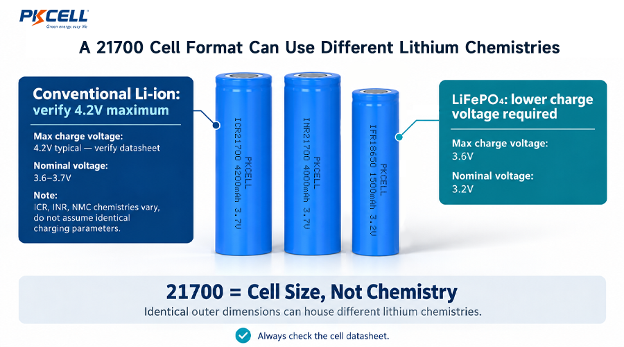
“21700” describes a cylindrical cell format approximately 21 mm in diameter and 70 mm long. It does not define one universal chemistry or charging voltage.
Many rechargeable 21700 cells use lithium-ion chemistries with a nominal voltage of 3.6V or 3.7V and a maximum charge voltage of 4.2V. However, some 21700 cells use lithium iron phosphate chemistry and require a lower charge voltage. High-voltage lithium-ion variants may also use a different upper limit.
Never select a charger from the “21700” size alone. Confirm the exact cell model, chemistry and maximum charge voltage in the approved cell specification.
The differences between common 21700 chemistries are covered in PKCELL’s
ICR21700 vs. IFR21700 comparison.
The 4.2V × S calculations in this guide apply only to cells specifically approved for a 4.2V maximum charge voltage.
What Do 1S, 2S and 3S Mean?
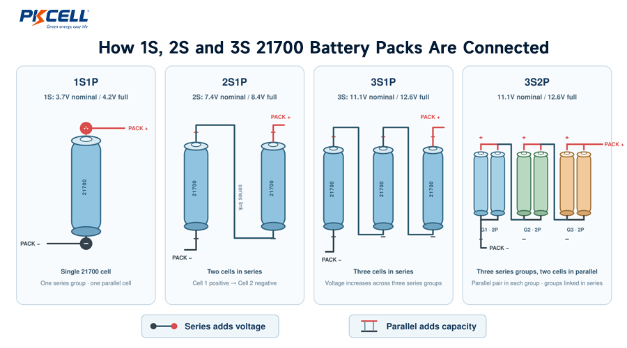
The letter S identifies how many cell groups are connected in series. Series connections add voltage. The letter P identifies how many cells are connected in parallel within each series group. Parallel connections add capacity and can increase current capability when the cells and interconnections are properly matched.
- 1S1P: one cell
- 1S2P: two cells in parallel
- 2S1P: two cells in series
- 2S2P: two parallel cells in each of two series groups, for four cells total
- 3S2P: two parallel cells in each of three series groups, for six cells total
A useful rule is:
For example, a 3S2P pack contains six cells. It has three voltage groups in series and two cells in each parallel group.
How to Calculate the Correct 21700 Charger Voltage
Charger voltage is determined by the number of series groups and the approved maximum voltage of each cell. It is not selected from the pack’s nominal voltage alone.
For conventional 4.2V lithium-ion cells, the common combinations are shown below.
| Configuration | Typical Nominal Voltage | Maximum Charge Voltage | Required Charger | Example Use |
|---|---|---|---|---|
| 1S | 3.6V or 3.7V | 4.2V | 4.2V CC/CV Li-ion charger | Portable lights, compact electronics |
| 2S | 7.2V or 7.4V | 8.4V | 8.4V CC/CV Li-ion charger | Monitoring devices, portable equipment |
| 3S | 10.8V or 11.1V | 12.6V | 12.6V CC/CV Li-ion charger | Robotics, GPS equipment, industrial devices |
A pack advertised as “12V lithium-ion” may actually be a 3S pack with an 11.1V nominal voltage and a 12.6V full-charge voltage. Therefore, a generic 12V power adapter is not automatically a suitable charger.
Does the P Value Change Charger Voltage?
No. Adding cells in parallel does not change the required charge voltage. Both a 2S1P and a 2S3P pack using 4.2V cells require an 8.4V charger.
The P value changes capacity and affects the allowable charging current. It can also change charge time, heat generation, BMS current requirements and the required connector or cable rating.
How to Choose the Right Charging Current
The maximum voltage answers only half of the charger-selection question. The charger’s current rating must also match the battery pack.
Cell manufacturers usually specify charging current in amperes or as a C-rate. A 1C current equals the rated amp-hour capacity of the cell or parallel group.
Example: One 5000mAh Cell
A 5000mAh cell has a capacity of 5Ah.
- 0.2C = 1A
- 0.5C = 2.5A
- 1C = 5A
These calculations explain the C-rate only. They do not prove that the cell is approved for every listed current. The actual limit must come from the cell specification.
How Parallel Cells Affect Charge Current
In a correctly designed 2P group, the charging current is shared between two matched cells. If a charger supplies 4A to a 1S2P pack, the idealized current is approximately 2A per cell.
Real current sharing is not perfectly equal. Cell resistance, temperature, state of charge, weld resistance and conductor layout all influence the current carried by each branch. Cells should be properly matched, as explained in the
battery cell matching guide.
Use the Lowest Current Limit in the Complete System
The selected charger current should not exceed any of these limits:
- The cell manufacturer’s permitted charging current
- The calculated pack limit for the approved parallel configuration
- The BMS maximum charge-current rating
- The current rating of the fuse, wiring and connector
- The safe thermal limit of the assembled pack and enclosure
- The device’s charging input or power-path limit
- Any reduced current required at high or low temperature
A larger charger-current number is not automatically better. A lower current may reduce heat and electrical stress, although it increases charging time. The final current should be verified using the intended enclosure, connector and operating environment.
Why the Charger Must Match the BMS
The charger controls the normal charging profile. The BMS monitors and protects the battery pack. These components must be coordinated, but they do not perform the same job.
A BMS may provide overcharge, over-discharge, overcurrent, short-circuit, balancing and temperature-protection functions. Depending on the design, it may also include fuel gauging, communication or wake-up control. PKCELL provides more detail about configurable protection and communication options on its
custom lithium-ion battery pack page.
Match the BMS Series Count
A 1S BMS monitors one series group, a 2S BMS monitors two, and a 3S BMS monitors three. A 2S charger should not be paired with a 1S pack or 1S BMS.
Check the BMS Charge-Current Rating Separately
Do not assume that a BMS with a high discharge-current rating accepts the same charging current. Charge and discharge limits may be different and should be listed separately in the specification.
Coordinate Charger Regulation and BMS Protection Thresholds
During normal charging, the charger should regulate the pack before the BMS overvoltage protection trips. The BMS is a protective layer, not the normal charge-termination control.
Charger accuracy, BMS measurement tolerance, cell imbalance, balancing behavior and wiring voltage drop should all be considered. PKCELL’s guide to
battery pack safety margins
explains why normal operating targets and protective thresholds should not be placed at the same boundary.
Include Temperature Monitoring
Lithium-ion charging limits depend on cell temperature. Where the risk assessment requires it, the pack should use a suitably located temperature sensor and defined charging response.
An NTC mounted far from the critical cell area may not represent the temperature that needs protection. See the guide to
NTC thermistor placement in lithium battery packs
for sensor-position and validation considerations.
Common 21700 Battery Charger Selection Mistakes
1. Choosing by Nominal Voltage
A 7.4V nominal 2S pack generally requires an 8.4V charger when it uses conventional 4.2V lithium-ion cells. Selecting a 7.4V output charger would not provide the required full-charge voltage.
2. Treating Every 21700 Cell as a 4.2V Cell
Cell format does not identify chemistry. A charger intended for a 4.2V lithium-ion cell must not be used for a lower-voltage LiFePO4 cell unless the charger is specifically configurable and correctly set.
3. Using a Power Adapter as a Charger
Matching the voltage printed on an adapter does not prove that it provides a correct CC/CV charging profile or safe charge termination.
4. Ignoring the BMS Charge Limit
A charger may be acceptable for the cells but still exceed the BMS charge-current rating or cause excessive heating in the protection MOSFETs.
5. Assuming More Parallel Cells Always Permit Proportionally More Current
The theoretical cell current may scale with the P count, but pack-level limits can still be set by the BMS, wiring, connector, welds, enclosure temperature or input circuitry.
6. Charging a Series Pack Without Suitable Group Monitoring
A series pack can become imbalanced. Monitoring and balancing requirements should be based on the exact cell, configuration, duty cycle and service-life target.
7. Overlooking Charging While the Device Is Running
When the product operates during charging, load current can affect charge termination, heat and charge-time calculations. The power-path design should be evaluated as part of the complete system.
Practical Charger Selection Examples
| Example Pack | Nominal Pack Rating | Charger Voltage | Current-Selection Approach | BMS Requirement |
|---|---|---|---|---|
| 1S1P, one 5000mAh cell | 3.7V, 5Ah | 4.2V | Based on one cell’s approved charge current and pack thermal limits | 1S protection matched to the cell and load |
| 1S2P, two 5000mAh cells | 3.7V, 10Ah | 4.2V | Based on the approved parallel-group limit, BMS and interconnections | 1S BMS rated for the total charge and discharge currents |
| 2S1P, two 5000mAh cells | 7.4V, 5Ah | 8.4V | Based on one cell’s limit because the same current passes through both series groups | 2S BMS with two-group monitoring |
| 2S2P, four 5000mAh cells | 7.4V, 10Ah | 8.4V | Based on the 2P group, BMS charge rating and pack thermal performance | 2S BMS sized for the complete pack |
| 3S2P, six 5000mAh cells | 11.1V, 10Ah | 12.6V | Based on the approved 2P limit and the lowest system component rating | 3S BMS with balancing and suitable temperature monitoring |
These examples assume conventional lithium-ion cells charged to 4.2V per series group. They are architecture examples, not universal charger specifications.
21700 Battery Charger Specification Checklist
Before purchasing or approving a charger, document:
- Exact 21700 cell manufacturer and model
- Cell chemistry and maximum charge voltage
- Pack configuration, such as 1S2P or 3S2P
- Nominal voltage, maximum charge voltage and capacity
- Normal and maximum charging current
- Required CC/CV behavior and termination conditions
- BMS series count and maximum charge-current rating
- Balancing method and activation conditions
- Charge-temperature range and NTC behavior
- Connector type, pinout, polarity and current rating
- Charging time target
- Whether the device operates while charging
- Input source, charger certification and target market
- Enclosure, ventilation and worst-case ambient temperature
Engineers developing a production pack should validate the charger, cells, BMS and device together rather than qualifying each component only in isolation. PKCELL’s
rechargeable battery product range
includes individual cells and example battery-pack configurations for early-stage evaluation.
Need a Charger-Matched 21700 Battery Pack?
Send PKCELL your required voltage, capacity, series-parallel configuration, charging time, load current, dimensions, connector and operating temperature. The engineering team can review the cell, BMS and charger as one integrated battery system.
Request a Battery Pack Quote
Explore Custom Battery Pack Services
Frequently Asked Questions
Can I charge a single 21700 battery with a 5V USB adapter?
Not directly. A 5V USB adapter is an input power source, not necessarily a lithium-ion charger. A suitable charging circuit must convert and regulate that input according to the cell’s required CC/CV profile, voltage, current, temperature and termination conditions.
What charger voltage does a 2S 21700 battery pack need?
A 2S pack made with conventional 4.2V lithium-ion cells requires an 8.4V CC/CV charger. Confirm the exact cell chemistry and specification before selecting the charger.
What charger voltage does a 3S 21700 pack need?
A conventional 3S lithium-ion pack uses a 12.6V charger because 4.2V × 3 equals 12.6V.
Can I use a 12V adapter to charge an 11.1V 21700 battery pack?
A typical 11.1V 3S lithium-ion pack requires 12.6V at full charge. A generic 12V adapter may use the wrong voltage and may not provide lithium-ion CC/CV control or correct termination. Use an approved 3S charger designed for the pack.
Does a 2P battery pack need twice the charging current?
No. A 2P pack can often accept more current than a 1P pack using the same cell, but it does not have to be charged at twice the current. Charge current should be selected from the approved cell data, BMS rating, desired charging time and pack-level thermal limits.
Does the BMS replace the 21700 battery charger?
No. The charger controls normal charging. The BMS provides monitoring and protective functions. A safe, reliable system requires both to be correctly specified and coordinated.
Can one adjustable charger be used for 1S, 2S and 3S packs?
Only when the charger is designed for those configurations and its voltage, current, chemistry profile and safety interlocks are correctly selected before connection. An accidental 3S setting applied to a 1S pack would be hazardous.
Conclusion
Choosing a 21700 battery charger begins with the exact cell specification and series count. For conventional 4.2V lithium-ion cells, multiply 4.2V by the S value: 4.2V for 1S, 8.4V for 2S and 12.6V for 3S.
Voltage alone is not enough. The charger current must stay within the lowest limit set by the cells, parallel configuration, BMS, wiring, connector, thermal design and device input. Charger regulation, BMS protection, balancing and temperature monitoring should then be validated together in the final product.
For an OEM project, share the complete electrical, mechanical and environmental requirements through the
PKCELL battery inquiry form
to receive a charger-compatible 21700 battery pack recommendation.
Post time: Sep-18-2026


