
18650 Discharge Current: Low Drain vs High Drain
Choosing an 18650 battery by capacity alone can create two opposite problems: a low-current device may carry unnecessary cost and lose runtime, while a high-current device may suffer voltage drop, overheating, early cutoff, or unstable performance. The correct choice starts with the device load profile and ends with verification of the complete battery pack.
Quick answer: For a low-drain device, prioritize usable capacity, low self-discharge, standby behavior, and the required service life after confirming that the cell can comfortably support every current peak. For a high-drain device, prioritize a verified continuous discharge rating, pulse conditions, low voltage sag, temperature rise, and a current path that includes the BMS, interconnects, wires, fuse, and connector.
There is no universal amp threshold that makes every 18650 a low-drain or high-drain cell. The classification is relative to the exact cell, device duty cycle, pack configuration, temperature, and allowed voltage drop.
18650 for Low-Drain Devices
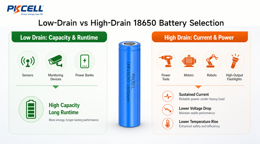
An 18650 for low drain is selected for a load that remains well below the cell’s approved current limit. Capacity and energy density usually matter more than maximum power. Typical design priorities include long runtime, low standby loss, predictable low-current operation, compact cost, and calendar life.
Examples can include monitoring equipment, backup electronics, power banks, low-output lighting, access-control devices, and some medical or IoT products. However, a device with a very low average current can still generate a demanding wireless transmission, camera, heater, valve, or motor pulse. Average current alone is not enough.
High-Drain 18650 Batteries
A high-drain 18650 is engineered to deliver higher current with acceptable voltage sag and heat under defined conditions. It may trade some capacity for lower resistance, stronger power delivery, and better thermal behavior. Common applications include power tools, motorized equipment, high-lumen flashlights, robotics, mobility devices, and other products with sustained or repeated heavy loads.
PKCELL’s high-rate battery range includes 18650 variants listed at 5C and 10C. These are distinct models, not interchangeable ratings for every 18650. The exact cell datasheet and approved thermal conditions remain decisive.
| Selection Area | Low-Current Device Priority | High-Current Device Priority | What to Verify |
|---|---|---|---|
| Capacity | Often a leading factor for runtime | Important, but secondary to safe power delivery | Minimum capacity and test conditions |
| Discharge current | Must exceed all real peaks with margin | Must support continuous and repeated peaks | Continuous rating, pulse definition, thermal limits |
| Internal resistance | Affects efficiency and low-voltage operation | Critical for voltage sag, heat, and current sharing | Measurement method, SOC, temperature, aging |
| Pack design | Standby consumption and cutoff behavior matter | Conductors, BMS, fusing, cooling, and connector matter | Full current path under representative load |
| Validation | Standby, pulse, runtime, and storage tests | Peak, stall, repeated-duty, low-SOC, and thermal tests | Production-intent pack in the actual device |
High capacity tells you how much charge a cell stores. Discharge-current capability tells you how quickly the device can draw that charge without exceeding the approved electrical and thermal limits.
Six Specifications That Determine 18650 Discharge Current
1. Continuous Discharge Rating
The continuous discharge rating is the maximum current permitted for sustained operation under the manufacturer’s defined conditions. It may depend on ambient temperature, cell temperature, cooling, cutoff voltage, and test fixture. A maximum rating is a boundary, not automatically the best normal operating point for an OEM design.
As a capacity-oriented example, PKCELL’s 3.7V 3300mAh 18650 product page lists a maximum continuous discharge current of 1.5C, or 4.95A. This does not make all 3300mAh cells equivalent, and it does not describe a different high-rate model.
2. Pulse Current and Duty Cycle
A pulse rating has engineering value only when pulse duration, rest interval, repetition count, starting state of charge, cutoff voltage, and temperature are defined. A cell that survives one short laboratory pulse may not tolerate a motor repeatedly starting every few seconds inside a sealed enclosure.
3. C-Rate
C-rate expresses current relative to capacity. It is useful for converting a specification, but it does not prove that two cells with the same C-rate will produce the same heat or voltage sag.
For example, 1.5C for a 3.3Ah cell equals 4.95A. A product listed at 10C must still be checked against its exact datasheet, temperature limit, cutoff, and any applicable pulse or continuous conditions.
4. Internal Resistance and Voltage Sag
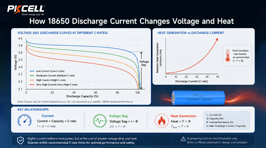
Current flowing through cell resistance and every connection in the pack causes voltage loss. A first-order estimate is:
If a 10A load sees 30mΩ of total effective resistance, the first-order voltage drop is about 0.30V. That is an illustration, not a model-specific cell claim. Actual behavior changes with state of charge, temperature, pulse length, electrochemical polarization, interconnects, BMS resistance, connector resistance, and aging.
PKCELL’s guide to cell internal resistance, power, heat, and pack consistency explains why the measurement method and complete pack layout matter.
5. Heat Generation
Resistive heat rises approximately with the square of current:
At the same resistance, doubling current creates roughly four times the resistive heating. This is why a current increase that appears modest on paper can require a different cell, more parallel paths, heavier conductors, improved spacing, or better cooling.
6. Temperature, State of Charge, and Age
Cold temperature generally increases voltage sag and reduces available power. Low state of charge leaves less voltage headroom above the device or BMS cutoff. Aging can reduce capacity and increase resistance. Test the candidate at the lowest expected SOC, coldest allowed operating condition, end-of-life resistance target, and highest credible load.
Start with the Device Load Profile
Do not request a battery using only device wattage or average current. Record current at the battery terminals with a sample rate fast enough to capture transients, and separate these values:
- Sleep current: current while the product is nominally inactive
- Average current: time-weighted current over a representative operating cycle
- Continuous current: the sustained load that determines thermal equilibrium
- Peak current: the highest transient during startup, transmission, illumination, heating, or actuation
- Peak duration: microseconds, milliseconds, seconds, or minutes
- Repetition and rest: how often a peak occurs and whether the pack cools between events
- Abnormal but credible current: motor stall, blocked fan, cold start, overload, or converter inrush
For a regulated load, battery current may rise as pack voltage falls. A 20W load does not draw a fixed current across the discharge curve. Ignoring converter efficiency, it needs about 5.4A at 3.7V but about 6.7A at 3.0V. Use the real converter efficiency and cutoff behavior for design calculations.
Measure startup and stall current directly where practical. Equipment labels and adapter ratings often do not reveal the battery-side transient that triggers voltage collapse or BMS protection.
18650 Selection by Device Type
| Device Type | Typical Load Shape | Likely Cell Priority | Validation Focus |
|---|---|---|---|
| Remote sensor or tracker | Very low standby plus radio, GPS, or camera pulses | Capacity, self-discharge, pulse stability | Cold transmission at low SOC; sleep-current budget |
| Power bank or backup electronics | Moderate, relatively steady converter load | Usable energy, efficiency, cycle life | Converter cutoff, port power, thermal rise |
| Medical or industrial monitor | Steady electronics with alarms, pumps, or communications | Reliability, traceability, required pulse margin | Worst-case accessory load and end-of-life runtime |
| Standard flashlight | Low to moderate continuous current | Runtime and stable output | Highest mode, low-SOC dimming, enclosure temperature |
| High-output flashlight | High continuous or stepped current | High drain, low sag, thermal control | Turbo duration, repeated use, hot enclosure |
| Power tool or motor | Large startup, variable load, possible stall | High drain, parallel sharing, robust current path | Stall, repeated bursts, BMS trip, connector heat |
| Robotics or mobility | Dynamic drive current plus electronics load | Power, energy, cycle life, pack-level protection | Acceleration, incline, cold start, regenerative events |
For more application context, compare PKCELL’s 18650 guide for flashlights and power tools. The contrast is useful because lighting often emphasizes runtime, while tools can prioritize short, high-power duty cycles.
A Practical 18650 Selection Workflow
Step 1: Define the Voltage Window
Confirm the system’s maximum input voltage, nominal operating voltage, undervoltage behavior, and required series count. A nominal 3.7V lithium-ion cell can reach 4.2V when fully charged, so nominal voltage is not a charger setting or fixed output.
Step 2: Capture the Complete Load Profile
Measure average, sustained, peak, peak duration, repetition, startup, stall, and standby current at the battery terminals. Repeat at relevant modes, temperatures, and supply voltages.
Step 3: Screen Cells by Verified Current Capability
Reject any cell whose approved continuous or defined pulse capability is below the requirement. Then compare minimum capacity, resistance, temperature curves, cycle life, dimensions, availability, and safety documentation. PKCELL’s cell datasheet guide for OEM pack design provides a field-by-field review sequence.
Step 4: Apply Design Margin
Do not operate a production design continuously at an attractive headline maximum without examining the test conditions. Margin must cover cell variation, aging, temperature, uneven current sharing, enclosure heat, measurement tolerance, and credible load transients. The required margin is application-specific.
Step 5: Choose Capacity and Parallel Count
After current capability is satisfied, size usable energy for runtime. Additional parallel cells can increase capacity and share current, but they also add size, weight, interconnects, matching requirements, and fault energy.
Step 6: Co-Design the BMS and Current Path
Specify the BMS continuous rating, overcurrent threshold and delay, short-circuit response, MOSFET loss, temperature sensing, fuse, busbars, welds, wires, connector, PCB copper, and enclosure. The battery can deliver only what the weakest approved element permits.
Step 7: Test Production-Intent Prototypes
Validate terminal voltage, individual cell-group voltage, current, cell temperature, BMS temperature, connector temperature, and cutoff behavior. Test hot, cold, high and low SOC, repeated pulses, maximum continuous load, credible faults, and aged samples when service-life power matters.
How Pack Configuration Changes Current Capability
Series cells increase pack voltage. Parallel cells increase capacity and ideally share load current.
A 20A pack load on a 2P configuration ideally asks each cell to supply 10A. Real sharing is not perfectly equal because of differences in cell resistance, weld quality, conductor geometry, temperature, state of charge, and aging. Use matched cells and a symmetrical current path, then verify group and cell temperatures.
The same pack can still fail even when the cell calculation looks acceptable. A high-resistance weld, thin nickel strip, undersized wire, warm connector, fuse, or BMS MOSFET can add voltage drop and heat. A low-current BMS can trip during a normal motor pulse; a very high protection threshold can leave conductors or cells insufficiently protected.
PKCELL’s 18650 battery-pack troubleshooting guide connects shutdown under load with overcurrent protection, voltage sag, weak cells, wiring, and BMS current rating. For an engineered pack, review the custom battery service early enough to align cell choice, protection, connector, structure, testing, and certification.
Common Selection Mistakes
- Choosing the highest mAh: capacity does not prove that the cell can support a motor, heater, high-output LED, or converter peak.
- Buying the highest amp label: extra current capability may not improve a low-drain device and can trade away capacity or cost.
- Using pulse current as continuous current: undefined or short pulse claims cannot support sustained load calculations.
- Ignoring low-SOC current: constant-power loads draw more current as battery voltage falls.
- Multiplying current by parallel count without margin: current sharing, temperature, and resistance are not perfectly equal.
- Sizing only the cells: the BMS, welds, busbars, fuse, wire, PCB, and connector can become the actual limit.
- Testing at room temperature only: cold start, hot enclosure, and aged cells can expose voltage-sag or thermal failures.
- Mixing cell models or histories: different capacity, resistance, SOC, batch, or age can cause imbalance and uneven load sharing.
- Using online listings instead of the exact datasheet: model revision, test conditions, and permitted application notes must match the supplied cell.
What to Send an 18650 Battery Supplier
A useful RFQ lets the engineering team compare capacity-oriented and high-rate candidates against the real device, not a guessed amp rating. Include:
- Product and use environment
- Nominal and full-charge voltage
- Device operating voltage range
- Average current
- Continuous current
- Peak current and duration
- Peak repetition and rest time
- Startup or stall current
- Required beginning-of-life runtime
- Required end-of-life runtime
- Operating and charging temperature
- Available size and weight
- Charge source and charge time
- BMS and communication needs
- Wire, connector, and NTC details
- Annual volume and launch schedule
- Target markets and certifications
- Prototype test acceptance criteria
Need Help Matching an 18650 to Your Load?
Send PKCELL your voltage window, measured load profile, runtime target, temperature range, pack space, charger, connector, expected volume, and certification needs. The team can compare capacity-oriented and high-rate 18650 options, then review the S/P configuration and protection strategy.
Frequently Asked Questions
What is a good 18650 discharge current?
There is no universal value. A good rating safely covers the device’s continuous and defined peak current with suitable margin at low SOC, temperature extremes, and end of life. Use the exact model datasheet and verify the assembled pack.
What is the difference between low-drain and high-drain 18650 batteries?
Low-drain selection usually emphasizes capacity and runtime after the required peaks are covered. High-drain selection emphasizes current capability, low voltage sag, manageable temperature, and repeated-duty performance, sometimes with a capacity tradeoff.
Can I use a high-drain 18650 in a low-current device?
Electrically it may be possible if voltage, size, terminals, protection, charger, and device requirements all match. However, it may provide no practical benefit and could offer less capacity or higher cost than a suitable energy-oriented cell.
Can a high-capacity 18650 power a high-current device?
Only if that exact cell’s continuous and pulse ratings, voltage sag, and thermal behavior meet the load. Capacity by itself does not establish current capability.
How do I calculate current from C-rate?
Multiply capacity in amp-hours by C-rate. A 3.3Ah cell at 1.5C corresponds to 4.95A. Then verify whether the rating is continuous or pulsed and review all test conditions.
Is pulse current the same as continuous discharge current?
No. Continuous current is intended for sustained operation under defined limits. Pulse current applies only to the stated pulse duration, rest period, repetition, SOC, cutoff, and temperature. An undefined pulse number should not drive a production design.
Why does an 18650 battery shut down under load?
Possible causes include cell voltage sag, an undersized BMS, overcurrent protection, weak or aged cells, low temperature, a high-resistance connection, an unsuitable connector, or a device peak that exceeds the pack design.
Do parallel 18650 cells increase discharge current?
Parallel cells can share current and increase capacity, but simple multiplication is only a screening calculation. Cell matching, resistance, interconnect symmetry, temperature, BMS, conductors, and fusing determine the safe finished-pack output.
Should I choose an 18650 by amps or mAh first?
First reject any cell that cannot safely support the full load profile. Then optimize capacity, size, weight, life, cost, and sourcing among the candidates that pass the electrical and thermal requirements.
Conclusion
The right 18650 battery is not automatically the cell with the highest capacity or the largest current label. A low-drain product needs enough peak capability plus efficient, reliable energy storage. A high-current product needs a verified continuous rating, defined pulse behavior, acceptable voltage sag, and controlled heat.
Start with measured average, continuous, peak, startup, and stall current. Check the exact cell datasheet, calculate per-cell current from the parallel count, and evaluate the complete path through interconnects, BMS, fuse, wiring, and connector. Then test representative packs at low SOC, temperature extremes, repeated duty, and end-of-life conditions.
Explore PKCELL’s 18650 battery range, review the broader 18650 selection guide, or send your load profile for an OEM battery recommendation and quotation.
Post time: Sep-01-2026


