
Case Study: Why a Lithium Battery Pack Shuts Down Under Load and How to Fix It
In many battery-powered products, a lithium battery pack may appear normal at rest but suddenly shut down when the device starts working. This case study explains the most common causes: BMS protection, voltage sag, overcurrent, weak cell groups, temperature limits, and wiring resistance.
Customer Case Background
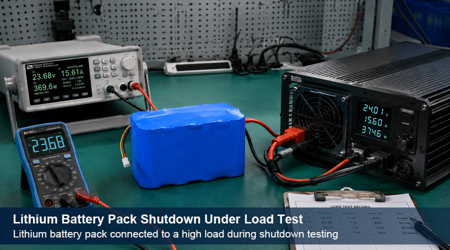
A customer used a lithium battery pack in a high-current device. The battery voltage looked normal before startup, but the pack shut down when the motor or inverter began drawing power. After disconnecting and reconnecting the charger, the battery recovered temporarily.
This is a typical sign that the battery pack is entering protection mode. For buyers developing portable equipment, industrial devices, energy storage products, or light electric vehicles, this issue should be solved at the battery design stage, not after mass production.
Need a battery pack for high-current equipment?
Main Finding: The Battery Was Not Matched to the Load
The shutdown was mainly caused by a mismatch between the load demand and the battery pack’s real discharge capability. A lithium battery pack is not selected by capacity alone. Voltage, continuous discharge current, peak current, BMS rating, cell chemistry, cable design, and connector resistance all matter.
For example, a 12V system running a 1,500W inverter may require more than 125A before surge current and efficiency loss are considered. If the BMS is rated for 100A continuous discharge, shutdown is expected.
Why a Lithium Battery Pack Shuts Down Under Load
1. BMS Overcurrent Protection
The battery management system monitors discharge current. If the device demands more current than the battery can safely provide, the BMS disconnects the pack to prevent overheating, cell stress, or short-circuit risk.
This is common in motors, pumps, power tools, electric mobility products, and inverter systems because startup current can be much higher than normal running current.
2. Voltage Sag Under Heavy Load
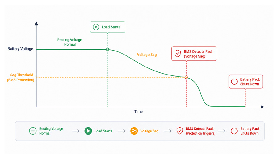
A battery can show healthy voltage at rest but drop sharply under load. This voltage sag may trigger undervoltage protection even if the battery still has remaining capacity.
Battery internal resistance, low temperature, aged cells, thin wires, long cable runs, and weak connectors can all increase voltage drop.
3. Weak or Imbalanced Cell Groups
In a series battery pack, one weak cell group can reach the low-voltage cutoff earlier than the others. The total pack voltage may still look acceptable, but the BMS will shut down the pack to protect the weakest cell group.
4. Temperature Protection
Cold conditions increase internal resistance and make voltage sag worse. High temperatures can also trigger BMS thermal protection, especially under long-duration high-current discharge.
5. Wiring and Connector Resistance
Loose terminals, undersized wires, low-quality connectors, or unsuitable fuse holders can create additional voltage drop. In high-current systems, even small resistance can cause shutdown.
Troubleshooting Checklist
| Test Item | What It Reveals | Recommended Action |
|---|---|---|
| Measure voltage at rest and under load | Shows whether voltage sag is causing cutoff | Record voltage directly at battery terminals during startup |
| Compare load current with BMS rating | Confirms overcurrent risk | Select a higher-current BMS or redesign the pack |
| Check cable and connector temperature | Identifies resistance and poor contact | Use proper cable gauge, connectors, and terminal design |
| Read BMS fault data | Shows the exact protection reason if available | Look for overcurrent, undervoltage, short-circuit, or temperature fault |
| Test with smaller load | Confirms whether the pack works within limits | Match the final pack to real peak current, not only average current |
How PKCELL Helps Prevent This Problem
For OEM and industrial buyers, the best solution is to design the battery pack around the real application. PKCELL supports rechargeable battery and custom battery pack projects with voltage, capacity, connector, casing, packaging, and BMS customization.
If your product needs stable discharge under heavy load, review these related PKCELL resources:
- Customized Battery Pack — for voltage, capacity, connector, casing, and pack structure customization.
- LiFePO4 Battery Pack — for safe, stable, and long-life battery pack applications.
- What Is a 18650 Lithium Battery Pack and How Does It Work? — useful background for pack structure and series-parallel design.
- How to Choose the Right Lithium Battery Pack — guidance for selecting capacity, voltage, and discharge performance.
Case Solution
In this case, the recommended solution was to redesign the battery pack with a higher discharge-current margin, suitable BMS protection settings, lower-resistance wiring, and connectors rated for the actual peak load.
For applications such as energy storage, emergency power, light electric vehicles, telecom devices, and industrial equipment, choosing a pack such as a 48V LiFePO4 battery pack or a fully customized pack may reduce current stress compared with a low-voltage system.
Planning a high-load battery project?
Send your voltage, capacity, current, connector, and application requirements to PKCELL for battery pack advice.
No. Bypassing the BMS is unsafe. The correct solution is to select the right cells, BMS, wiring, and connector design for the load.
Conclusion
A lithium battery pack shuts down under load when the application exceeds the safe operating range of the cells, BMS, or pack structure. The root cause is usually not just “bad battery quality,” but a mismatch between load demand and battery design.
For OEM projects, the safest path is to confirm peak current, working temperature, voltage range, connector type, and runtime requirements before selecting the battery pack.
Post time: Jul-28-2026


