
NTC Thermistor Placement in Lithium Battery Packs
An NTC thermistor can only protect the temperature it is able to sense. If it is mounted on a cool enclosure wall, isolated by thick foam, or heated mainly by the BMS instead of the cells, the reading may look reasonable while the critical area of a lithium battery pack is already much hotter or colder.
Place an NTC thermistor in firm, repeatable thermal contact with the cell or cell group that best represents the temperature limit being protected. For discharge protection, this is often a predicted internal hot spot. For cold-charge protection, it may be the cell location most exposed to low ambient temperature. Large or thermally uneven packs usually need multiple sensors. Confirm every location with thermal mapping and production-intent charge, discharge, fault, and environmental tests.
There is no universal point that is correct for every 1S pouch battery, cylindrical 18650 array, 21700 pack, or multi-cell module. Good NTC thermistor placement begins by defining the measurement objective, predicting heat flow, and identifying where a delayed or biased reading would create the greatest risk.
What an NTC Thermistor Does in a Battery Pack
NTC means negative temperature coefficient. As an NTC thermistor becomes warmer, its resistance decreases. A charger, protection circuit, BMS, or host controller usually reads that resistance through a divider or dedicated temperature-sense input and converts it into a temperature or threshold decision.
Depending on the system architecture, the reading may be used to:
- Permit, reduce, suspend, or stop charging
- Reduce discharge current or disconnect the load
- Control a fan, heater, pump, or other thermal hardware
- Report pack temperature to the host device
- Log thermal history or trigger a diagnostic fault
- Support state and performance estimation
A commonly used component value is 10 kΩ at 25°C, but that does not make every 10 kΩ NTC interchangeable. The BMS or charger must match the thermistor’s resistance at 25°C, beta value or full resistance-temperature curve, tolerance, divider network, and expected threshold behavior.
The correct NTC is the sensor-and-circuit combination that produces the required trip behavior across component tolerances and real pack temperatures.
Start With the Protection Goal, Not a Favorite Location
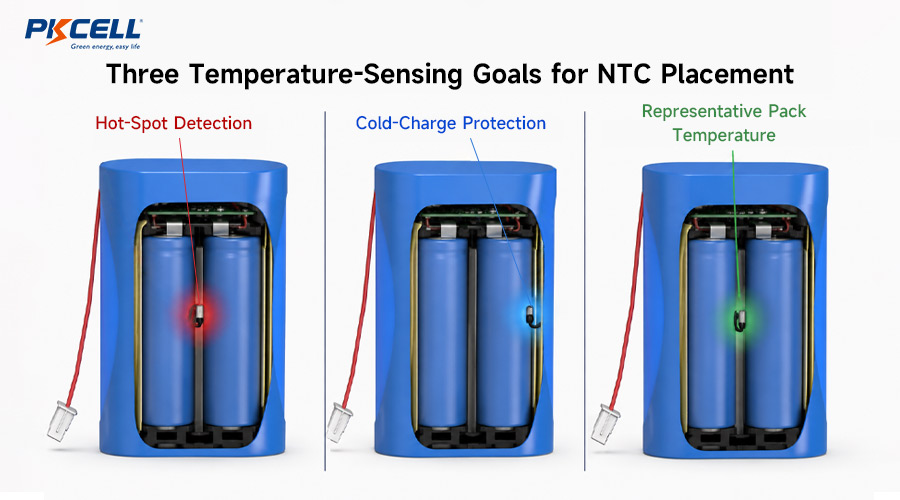
Goal 1: Detect the hottest cell during discharge
High discharge current creates heat in cells, interconnects, fuses, connectors, and BMS power components. Cells near the center of a dense pack may have less access to the enclosure or cooling airflow, but the hottest location depends on geometry, current distribution, cell variation, cooling path, and nearby electronics.
A sensor used for overtemperature protection should be coupled to a location that tracks the limiting cell quickly enough for the BMS to act before the real cell temperature exceeds its permitted boundary. For high-rate applications, review PKCELL’s high-discharge lithium-ion battery solutions together with the pack’s thermal and current-path requirements.
Goal 2: Prevent charging when any cell is too cold
The hottest point is not always the right point for charge qualification. In a pack entering a warm room from a cold environment, outer cells may remain colder than a sensor buried near warm electronics. If the charger sees only the warm sensor, it may permit charging before the coldest cell has entered the approved charging range.
Cold-charge protection therefore requires analysis of the coldest credible cell location, thermal soak, airflow, enclosure interfaces, heaters, and time delay between ambient and cell temperatures. In some products, separate sensors are justified for hot-discharge and cold-charge decisions.
Goal 3: Measure a representative pack temperature
A fuel gauge or host display may need a stable temperature representative of most cells rather than the most extreme point. That is a different objective from safety protection. One sensor value should not be assumed to satisfy hot-spot protection, cold-charge qualification, thermal-control feedback, and user-facing temperature reporting unless testing demonstrates that it can.
Where to Place an NTC on Different Pack Formats
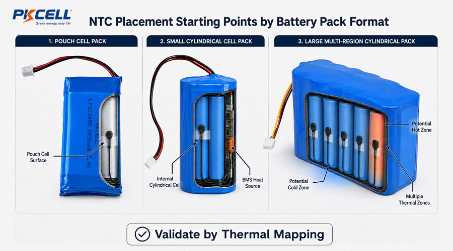
| Pack format | Useful starting location | Primary risk to check | Validation priority |
|---|---|---|---|
| Single pouch cell | On the broad cell surface at a thermally representative or mapped hot region | Sensor influenced by the PCB, poor contact, pressure point, or delayed surface response | Charge/discharge mapping across the pouch surface and tabs |
| Small cylindrical pack | Against a cell can in the predicted hottest internal group | Cool edge placement missing heat in the center of the array | Compare center, edge, terminal, and BMS-side temperatures |
| Large cylindrical array | Multiple sensors across thermal zones, including likely hot and cold regions | One sensor averaging away local gradients | Full-pack mapping under airflow, enclosure, and worst-case load |
| Prismatic pack | Cell face or interface identified by thermal characterization | Compression hardware or cooling plate biasing the reading | Surface-to-core correlation and sensor response delay |
| Pack with high-power BMS | Cell sensor plus a separate sensor near MOSFETs, shunt, fuse, or connector if required | Electronics heat being mistaken for cell temperature, or vice versa | Independent cell-zone and electronics-zone trip behavior |
These locations are screening points, not release criteria. The final location should follow measured thermal behavior in the actual enclosure. PKCELL’s custom lithium-ion battery pack options include application-specific PCM/BMS, NTC, wire, connector, and structural configurations.
How Many NTC Thermistors Does a Pack Need?
Sensor count should follow thermal risk and diagnostic coverage, not only cell count. A compact, low-current 1S pack with a uniform enclosure may be adequately represented by one well-coupled sensor. A larger pack with multiple parallel groups, uneven cooling, high current, or separated heat sources can require several sensors.
Consider additional NTCs when the pack has:
- Multiple cell rows or physically separated modules
- Strong airflow or cooling on only one side
- An enclosure wall exposed to outdoor cold or solar heating
- High-rate charge or discharge
- A heater, cooling plate, fan, or thermal interface
- High-power MOSFETs, a shunt, fuse, or connector near the cells
- Parallel branches with potentially different current paths
- A safety or availability requirement that justifies sensor redundancy
The BMS must define how multiple readings are used. Examples include taking the highest temperature for discharge derating, the lowest temperature for charge permission, checking the spread between sensors, and using separate limits for cells and power electronics.
PKCELL’s battery pack technology and BMS capabilities include temperature monitoring with NTC thermistors alongside balancing and configurable communication options.
Thermal Contact: Make the Sensor Read the Cell
An electrically correct NTC can still produce a poor temperature signal if it is thermally isolated. The sensor should have repeatable contact with the intended surface while remaining electrically insulated and mechanically protected.
Good mounting practices
- Use a thin, qualified electrically insulating interface where insulation is required.
- Select adhesive, tape, or potting material that remains stable across temperature, aging, humidity, and vibration.
- Provide controlled contact pressure without crushing the thermistor, cell sleeve, pouch, or lead insulation.
- Route leads so assembly movement cannot pull the sensor away from the cell.
- Keep the sensor away from sharp nickel edges, busbars, weld projections, and pinch points.
- Define the exact placement with drawings, dimensions, photographs, and work instructions.
- Inspect adhesion and position after pack assembly, not only before wrapping or enclosure closure.
Common sources of measurement bias
- Thick foam or air gaps between the NTC and cell
- Mounting on a cool plastic holder instead of the intended cell
- Placing the NTC too close to a hot BMS component
- Heavy potting that slows the response or couples the sensor to the enclosure
- Metal tape or exposed leads creating an electrical insulation risk
- Inconsistent sensor position between production units
- Lead conduction carrying heat toward or away from a small bead sensor
A thermistor measures its own temperature. Mounting design determines how closely that temperature follows the cell or component you intend to protect.
Do Not Let BMS Heat Distort the Cell Reading
Protection MOSFETs, current-sense resistors, balancing resistors, connectors, fuses, and PCB copper can become local heat sources. A cell NTC placed near these components may trip early even when cells remain cool. Moving it too far away can create the opposite problem by leaving power electronics unmonitored.
The better solution is to separate measurement objectives where the risk justifies it:
- Use one or more sensors thermally coupled to critical cell zones.
- Use a separate PCB or component sensor for BMS power-stage protection.
- Apply different thresholds and time behavior for cell and electronics temperatures.
- Confirm that firmware identifies sensor channels correctly and reacts predictably to each fault.
Need help defining NTC locations and BMS behavior?
Send PKCELL your pack configuration, cell model, charge and discharge currents, enclosure drawing, operating temperatures, cooling method, charger interface, and certification targets. The engineering team can review sensor count, placement, wiring, and prototype validation requirements.
NTC Wiring and BMS Input Design
Sensor placement and electrical design must be developed together. Check the BMS or charger documentation for the supported NTC resistance, beta or curve, pull-up network, input range, filtering, diagnostic capability, and charge-control thresholds.
- Reference connection: Follow the controller’s recommended grounding and divider arrangement.
- Lead resistance: Usually small compared with a 10 kΩ thermistor, but it should still be considered for long harnesses or lower-resistance sensors.
- Noise: Route high-impedance temperature signals away from switching nodes, high-current conductors, and noisy communication lines.
- Filtering: Reduce noise without hiding a meaningful temperature rise.
- Open/short detection: Define safe behavior for broken wires, crushed insulation, connector faults, and implausible readings.
- Connector pinout: Prevent the NTC pin from being confused with identification, communication, or balance connections.
- Wake and sleep states: Confirm when temperature is measured and whether protection remains available in charging, storage, or low-power modes.
Some three-terminal battery packs use the third terminal for an NTC, but others may use a fixed identification resistor or a different function. The pack and host interface must be specified rather than inferred from the number of terminals.
Set Thresholds From Cell Limits and Sensor Error
BMS thresholds should not simply equal the cell’s absolute temperature boundary. A practical protection design accounts for sensor tolerance, divider tolerance, ADC error, placement offset, surface-to-core difference, response delay, thermal overshoot, and control latency.
Thresholds may also need hysteresis so charging or discharging does not repeatedly switch on and off near a boundary. Derating can be preferable to abrupt shutdown in some products, but the strategy must remain within the approved cell, charger, pack, and product limits.
Validate Placement With Thermal Mapping
CAD geometry and simulation can identify candidates, but prototype testing should confirm the final position. Instrument early packs with more thermocouples than the production design will contain. Compare those reference points with each NTC channel and the BMS-reported temperature.
Recommended validation conditions
- Maximum continuous discharge and repeated peak loads
- Maximum qualified charge rate
- Low-SOC operation
- Maximum and minimum ambient temperatures
- Cold-soaked pack followed by a charge request
- Hot-soaked pack followed by discharge or charging
- Restricted airflow, blocked vent, or expected installation orientations
- Heater, fan, or cooling-system faults where applicable
- Aged cells or a justified end-of-life resistance model
- Connector, fuse, weld, and BMS heating under maximum current
Review both steady-state temperature and time response. A sensor that eventually reaches the correct temperature may still be unsuitable if the cell exceeds its limit before the BMS receives a trip-level reading.
Correlate, do not merely compare
For each NTC, document the maximum observed difference from the protected point, the delay during rapid heating and cooling, unit-to-unit variation, and the effect of assembly tolerances. Use these results to establish thresholds, diagnostics, process controls, and any required calibration.
A Practical NTC Placement Workflow
- Define every thermal decision. Identify which sensor controls charging, discharge derating, shutdown, heating, cooling, logging, or host reporting.
- Map potential heat sources and cold zones. Include cells, interconnects, MOSFETs, shunt, fuse, connector, airflow, enclosure walls, and heaters.
- Select candidate locations. Choose positions for predicted cell hot spots, cold-charge zones, and power electronics as required.
- Select the NTC and circuit. Match R25, beta or curve, tolerance, BMS input, divider, filtering, and diagnostic behavior.
- Design the attachment. Specify insulation, adhesive, pressure, lead routing, strain relief, and protection from sharp conductors.
- Instrument prototypes broadly. Add reference thermocouples beyond the intended production NTC count.
- Run worst-case tests. Cover charge, discharge, ambient extremes, transient loads, faults, orientations, and aged conditions.
- Correlate and set margins. Quantify offset, delay, tolerances, overshoot, and unit variation before setting limits.
- Validate fault handling. Test NTC open, short, disconnected pack, swapped connector, and implausible sensor differences.
- Lock the production process. Control part number, placement dimensions, adhesive, tape, lead routing, inspection, and functional tests.
PKCELL’s custom battery pack service supports application-specific cell selection, pack structure, wires, connectors, protection circuits, BMS functions, and thermal design. OEM teams can also review the consumer electronics battery development workflow.
Common NTC Placement Mistakes
- Placing the only NTC where assembly is easiest rather than where risk is highest
- Assuming the center of every pack is automatically the hottest point
- Using the hot-spot sensor to qualify cold charging without cold-soak testing
- Mounting the sensor on a plastic holder with weak thermal contact to the cell
- Allowing BMS heat to bias a sensor intended to measure cell temperature
- Using thick foam, potting, or tape without measuring response delay
- Selecting a 10 kΩ NTC without confirming its beta curve and charger compatibility
- Ignoring sensor, resistor, ADC, attachment, and unit-to-unit tolerances
- Providing no defined response to an open or shorted thermistor
- Validating only at room temperature and beginning of life
- Changing adhesive, cell holder, enclosure, BMS, or NTC supplier without thermal requalification
What to Include in a Custom Battery Pack Inquiry
- Cell model, chemistry, format, and series/parallel configuration
- Maximum charge, continuous discharge, and pulse currents
- Enclosure drawing, cell arrangement, mounting orientation, and available space
- Operating, charging, and storage temperature ranges
- Cooling, airflow, heater, insulation, and potting details
- BMS or charger model and supported thermistor requirements
- Required NTC connector pins, lead length, and communication interface
- Expected product life, annual volume, target markets, and certifications
Available cells and example configurations can be reviewed in PKCELL’s rechargeable battery product range.
Frequently Asked Questions
Where should an NTC thermistor be placed in a lithium battery pack?
Place it in repeatable thermal contact with the cell or zone that represents the protected temperature limit. This may be an internal hot spot for discharge protection or an exposed cold cell for charge qualification. Confirm the location with thermal mapping and worst-case tests.
Should the NTC be placed in the middle of the battery pack?
The middle is a useful candidate when internal cells receive less cooling, but it is not universally correct. Airflow, enclosure contact, current paths, BMS heat, heaters, and external temperature exposure can move the hottest or coldest point.
How should an NTC be attached to a cell?
Use a thin, electrically insulating, thermally effective attachment that remains stable through temperature, vibration, humidity, and aging. Prevent air gaps, lead strain, sharp-edge damage, and excessive pressure on the cell or sensor.
Is one NTC enough for a battery pack?
It may be enough for a small, thermally uniform, low-power pack after validation. Larger, high-current, multi-zone, actively heated, or unevenly cooled packs may need multiple sensors for hot cells, cold cells, and BMS components.
Can any 10 kΩ NTC work with a battery charger?
No. The resistance at 25°C is only one parameter. The beta value or full curve, tolerance, divider network, charger thresholds, and wiring configuration must all be compatible and verified across worst-case tolerances.
What certifications and compliance documents can PKCELL support?
PKCELL operates quality and environmental management systems including ISO 9001 and ISO 14001. Depending on the exact cell, custom battery-pack configuration, destination market, and project scope, available product or transport support may include UL 1642, CB/IEC 62133, CE, RoHS, REACH, UN 38.3, MSDS, KC, PSE, UKCA, and other project-specific documents.
Certification coverage must be confirmed for the exact production design; a certificate for one cell or pack does not automatically cover every customized configuration. Review PKCELL’s battery certificates and compliance information and include the required standards in your RFQ.
What is PKCELL’s manufacturing capacity for bulk battery orders?
PKCELL’s published company information describes a 28,000 m² manufacturing facility, more than 20 automated production lines, and a professional team of more than 400 people. Current public product content cites annual production capacity of up to 500 million battery units.
Available capacity for a custom pack with NTC sensing depends on its cell format, BMS, harness, connector, enclosure, testing, certification, and forecast. Purchasing teams should request a project-specific line-capacity and delivery review.
How can I get a bulk quote for a battery pack with NTC monitoring?
Provide the battery chemistry, cell model, series/parallel configuration, nominal voltage, capacity, continuous and peak current, pack dimensions, NTC quantity, R25 value, beta or resistance-temperature curve, tolerance, lead length, connector pinout, BMS or charger model, temperature thresholds, annual quantity, first-order quantity, destination country, certification requirements, and requested Incoterm.
What is the MOQ, and can buyers order samples first?
Samples are available for evaluation, subject to the selected product and project status. Some PKCELL product pages state a minimum formal-order value starting from USD 500, while the actual MOQ depends on the battery model, NTC harness, customized BMS, enclosure, tooling, certification, and production process.
Ask for separate sample, pilot-build, and mass-production quantities so thermal correlation and device testing can be completed before volume release.
Can PKCELL customize the NTC type, quantity, placement, and connector?
Yes. PKCELL can support application-specific NTC quantity, nominal resistance, beta curve, tolerance, lead length, insulation, connector, BMS input, and mounting location. The final specification should define which sensor protects the hottest discharge zone, the coldest charging zone, or the BMS power stage.
What NTC quality controls should be included in a bulk purchase specification?
Define the approved thermistor part number, resistance and beta tolerance, supplier, lead and connector specification, mounting coordinates, adhesive or tape, insulation, wire routing, pull protection, and inspection method. Production testing should check NTC open and short faults, room-temperature reading, channel identification, charger or BMS response, and traceability.
Conclusion: Validate the Temperature You Need to Protect
Effective NTC thermistor placement starts with a clear thermal objective. Identify the likely hot and cold zones, separate cell sensing from BMS component sensing where necessary, create reliable thermal contact, and design the input circuit for the exact thermistor. Most importantly, correlate the NTC reading with instrumented cell temperatures under production-intent worst-case conditions.
Develop a Custom Battery Pack With Validated NTC Placement
Share your cell configuration, load profile, temperature range, enclosure, charger, BMS, cooling method, volume, and compliance requirements with PKCELL. Our team can help evaluate sensor placement, pack protection, wiring, and prototype validation.
Post time: Aug-10-2026


