
NiMH Battery Pack Charging Design: Delta-V, Temperature and Timer Control
Reliable NiMH battery charging requires more than applying a fixed voltage or running the charger for a preset number of hours. During charging, voltage changes near full charge can be subtle, temperature behavior depends on the pack and environment, and aged or partially charged batteries may respond differently from new cells. A robust NiMH charging design therefore combines voltage-trend detection, temperature monitoring and an independent safety timer.
Why NiMH Charging Needs Multiple Control Signals
NiMH batteries are commonly charged using a controlled current. Unlike lithium-ion batteries, they do not rely on one fixed final voltage followed by a universal current-taper phase. The battery voltage varies with charging current, cell temperature, internal resistance, age and state of charge.
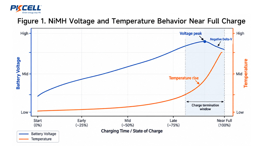
As a NiMH cell approaches full charge, its ability to store incoming energy decreases. More of the charging energy begins to appear as heat. At the same time, the terminal voltage may reach a peak and then decrease slightly.
This behavior gives the charger several useful signals to monitor:
- Pack voltage and voltage trend
- Negative Delta-V after the voltage peak
- Battery temperature
- Rate of temperature rise
- Actual charging current
- Total elapsed charging time
- Battery presence and plausible pack voltage
- Thermistor open-circuit or short-circuit faults
A charger that combines these signals is generally more robust than one that depends on only a single voltage threshold.
PKCELL provides multiple NiMH battery pack configurations for OEM applications. The correct charging algorithm should always be matched to the selected cell type, pack voltage, capacity, series count and temperature-sensing arrangement.
How Negative Delta-V Charging Works
Understanding the Voltage Peak
During constant-current charging, the voltage of a NiMH cell normally rises as its state of charge increases. Near full charge, the voltage reaches a peak. Under suitable charging conditions, the voltage then falls slightly.
This small decline is known as negative Delta-V or -ΔV.
The charger stores the highest valid voltage measured during the fast-charge stage. When the filtered battery voltage falls below this peak by a qualified amount for a defined period, the controller can terminate fast charge or move to another approved charging state.
Why Delta-V Is Difficult to Detect
The voltage drop can be small, especially compared with the total battery pack voltage. A multi-cell NiMH pack may have a total voltage of several volts while the useful change at full charge may be only a few millivolts per cell.
This means charger accuracy depends on more than the firmware threshold. Important factors include ADC resolution, voltage-reference stability, current regulation, electrical noise, wiring resistance and filtering.
Use a Per-Cell Threshold
Delta-V limits are normally defined per cell and then evaluated for the number of cells connected in series.
The exact per-cell value should come from the selected cell specification and project validation. A threshold taken from another cell or reference charger should not automatically be reused.
Avoid False Delta-V Detection
Voltage drops can also be caused by current switching, loose connections, connector resistance, load changes or measurement noise. A robust charger should therefore avoid terminating fast charge because of one low ADC reading.
- Use an initial holdoff period before enabling Delta-V detection.
- Require a minimum battery voltage before peak tracking begins.
- Measure voltage at a consistent point in the charging cycle.
- Use averaging or appropriate digital filtering.
- Require several consecutive qualifying samples.
- Reject implausible voltage changes.
- Prevent immediate automatic restart after charge completion.
Negative Delta-V should be interpreted as a qualified voltage trend, not as a single final battery voltage.
Why Charge Rate Affects Delta-V Detection
Negative Delta-V tends to be easier to identify during moderate or faster charging because the voltage peak and thermal response are more pronounced. At lower charge rates, the change may become weak and difficult to separate from normal measurement noise.
This does not mean that low-rate charging is automatically safer. A long timer designed around a fully discharged battery can overcharge a battery that was already partially charged when connected.
Temperature Control in a NiMH Charger
Temperature monitoring is an important independent protection path. It helps the charger determine whether the battery is suitable for fast charging and can also indicate that the battery is approaching full charge.
Start-Temperature Qualification
Before applying fast-charge current, the charger should confirm that the battery temperature is within the approved charging range. A pack taken directly from a hot operating environment may need time to cool before fast charging begins.
Similarly, charging outside the permitted low-temperature range may require reduced current or complete charge inhibition.
Absolute Temperature Cutoff
An absolute temperature limit should remain active during the charging process. If the measured battery temperature exceeds the approved limit, charging should stop regardless of whether Delta-V has been detected.
The correct cutoff depends on the selected cells and pack design. The value should not be copied from a generic reference circuit.
Rate of Temperature Rise: dT/dt
Near full charge, the rate at which battery temperature increases may become more pronounced. The controller can evaluate this temperature slope using:
A qualified dT/dt threshold can provide an additional termination signal. However, the result depends strongly on sensor location, cell format, charging rate, enclosure design, airflow and ambient temperature.
For this reason, dT/dt should be validated with the final battery pack and enclosure rather than using a universal threshold.
Thermistor Placement Is Critical
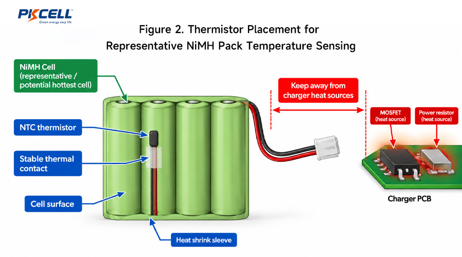
The temperature sensor should measure the battery rather than the surrounding air or charger electronics. A poorly positioned thermistor may respond too slowly or report heat generated by another component.
- Place the thermistor in stable thermal contact with a representative cell.
- Consider the cell most likely to become hottest during charging.
- Keep the sensor away from charger MOSFETs, transformers and power resistors.
- Use electrical insulation where required.
- Make the mechanical contact repeatable from pack to pack.
- Detect open-circuit and short-circuit thermistor faults in firmware.
- Consider multiple temperature sensors for larger or thermally uneven battery packs.
Timer Control as an Independent Safety Backup
Every NiMH charging design should include a maximum charging-time limit. The timer provides protection if the primary voltage or temperature termination method does not operate as expected.
Possible causes of missed termination include weak Delta-V behavior, poor sensor contact, unusual battery aging, firmware errors, ADC noise or a battery pack that never develops the expected signal.
A simple starting estimate for ideal charging duration is:
However, real charging is not perfectly efficient. The released timer therefore needs an appropriate allowance based on the actual cell chemistry, charging current and manufacturer’s requirements.
The maximum timeout should be validated under worst-case conditions rather than calculated using one generic multiplier.
Important Timer Design Rules
- Count charging time only when meaningful charging current is actually flowing.
- Use separate time limits for precharge, fast charge and top-off stages.
- Do not continually reset the safety timer after brief power interruptions.
- Control automatic restart behavior after a completed charge.
- Treat a timeout as a fault condition rather than proof that the battery is fully charged.
- Verify firmware timing and oscillator tolerance.
How Delta-V, Temperature and Timer Control Work Together
| Control Method | Main Purpose | Main Limitation | Recommended Role |
|---|---|---|---|
| Negative Delta-V | Detect the voltage decline after the charging peak | Signal may be small or noisy | Primary or supporting fast-charge termination method |
| dT/dt | Detect increasing heat generation near full charge | Depends heavily on thermistor placement and thermal design | Independent termination signal |
| Absolute temperature | Prevent charging under unsafe thermal conditions | Sensor response may lag behind cell temperature | Always-active safety limit |
| Maximum timer | Stop charging if other detection methods fail | Does not directly measure state of charge | Independent backup protection |
In a robust charger, several conditions can end fast charge. A qualified Delta-V event or validated temperature-rise event may represent normal charge completion, while an excessive temperature, sensor failure or expired safety timer should normally be treated as a fault.
A Practical NiMH Charger State Machine
Separating the charging sequence into clear states makes the algorithm easier to validate and helps distinguish normal charge completion from fault conditions.
| Charging State | Main Action | Typical Exit or Fault Conditions |
|---|---|---|
| Battery detection | Check pack presence, voltage range, polarity and temperature sensor | Wrong battery, implausible voltage or sensor fault |
| Temperature qualification | Confirm that battery temperature is suitable for charging | Battery too hot or too cold |
| Precharge | Apply reduced current when permitted for a deeply discharged battery | Voltage recovery, temperature fault or precharge timeout |
| Fast charge | Apply controlled current and monitor voltage, temperature and time | Qualified Delta-V, dT/dt, temperature limit or timeout |
| Top-off | Apply a limited lower-current stage if approved for the selected cells | Top-off timeout or temperature limit |
| Charge complete | Stop charging or enter an approved maintenance method | Battery removal or controlled restart |
| Fault | Disable charging current and record the abnormal condition | Manual reset, battery removal or approved recovery procedure |
Worked Example: Six-Cell 2000mAh NiMH Pack
Consider a hypothetical 7.2V nominal NiMH battery pack consisting of six 2000mAh cells connected in series.
If the selected cells are approved for a 0.5C charging rate, the charging current would be:
Charging current = 2.0Ah × 0.5C = 1.0A
The series connection increases the total pack voltage but does not increase the ampere-hour capacity.
The charger designer would then confirm the approved per-cell Delta-V condition, temperature range, dT/dt criteria, maximum charge time and optional top-off method from the selected cell specification.
The pack-level Delta-V logic would account for all six series cells, while an independently monitored thermistor and timer would remain active during the fast-charge stage.
This is an example of the design process, not a universal charging specification for every 7.2V 2000mAh NiMH battery pack.
Pack-Level Factors That Affect Charging Behavior
Cell Matching
Cells connected in series should be reasonably matched in capacity, internal resistance and state of charge. If one cell reaches full charge substantially earlier than the others, it may enter overcharge while the total pack voltage still appears acceptable.
Series Cell Count
A higher series count increases total battery voltage and changes the measurement range required by the charger. The ADC and resistor network should provide enough resolution to detect a small per-cell voltage change across the full pack voltage.
Wiring and Connector Resistance
Voltage drops across wires, connectors, fuses and contacts can influence the measured battery voltage, especially when charging current changes. The sensing method should therefore be consistent and appropriately placed.
Pack Thermal Design
Cell arrangement, heat-shrink material, spacing, enclosure ventilation and nearby electronics affect the temperature profile seen by the thermistor. Charging validation should therefore use the final battery construction whenever possible.
For projects that require specific series and parallel configurations, connectors, lead lengths, temperature sensors or custom dimensions, PKCELL provides custom battery pack development for OEM applications.
Common NiMH Charging Design Mistakes
- Using one fixed pack voltage as the only full-charge cutoff.
- Copying a Delta-V threshold from another NiMH cell without validation.
- Using a per-cell Delta-V value directly on a multi-cell battery pack.
- Allowing one noisy voltage sample to terminate charging.
- Using Delta-V at a charging rate where the signal is too weak to detect reliably.
- Placing the thermistor away from the battery cells.
- Installing the sensor beside charger components that generate heat.
- Failing to detect an open or shorted thermistor.
- Using a timer calculated only for a fully discharged battery.
- Automatically restarting full fast charge after every brief power interruption.
- Leaving an excessive trickle charge applied indefinitely.
- Testing only new batteries at room temperature.
Production Charger Validation Checklist
- Test new and aged battery packs.
- Test fully discharged, partially charged and nearly full batteries.
- Validate at low, normal and high approved ambient temperatures.
- Confirm charging-current tolerance.
- Verify Delta-V detection with maximum expected electrical noise.
- Test ADC and voltage-reference tolerance.
- Test thermistor tolerance and thermal contact variation.
- Simulate thermistor open-circuit and short-circuit faults.
- Test battery removal and reinsertion during charging.
- Verify behavior after temporary power loss.
- Force the primary termination method to fail and verify the safety timer.
- Confirm that excessive temperature always stops charging.
- Repeat the tests inside the final product enclosure.
During testing, record battery voltage, charging current, temperature, ambient temperature, elapsed time and the reason the charger stopped. This makes it easier to distinguish normal completion from a safety fault and provides evidence for future design changes.
Engineers can review PKCELL’s NiMH rechargeable battery options and industrial NiMH batteries when evaluating cell formats and capacity ranges.
PKCELL also supplies NiMH and NiCd battery chargers for compatible battery configurations.
Information to Send for a Custom NiMH Battery Project
Providing complete charging and application requirements early in development helps reduce battery and charger compatibility issues.
- Required battery voltage
- Required battery capacity
- Series and parallel configuration if already defined
- Desired charging time
- Available charging current
- Operating and charging temperature range
- Maximum battery dimensions
- Continuous and peak discharge current
- Required connector and wire length
- Thermistor or temperature-sensing requirements
- Application duty cycle
- Expected cycle life
- Certification and target markets
- Estimated annual quantity
For project-specific support, these details can be submitted through the PKCELL contact page.
Frequently Asked Questions
What is negative Delta-V in NiMH charging?
Negative Delta-V is the small decrease in battery voltage that can occur after a NiMH cell reaches its charging-voltage peak. A charger can use a qualified and filtered version of this decline as an end-of-charge signal.
Can negative Delta-V be the only NiMH charging cutoff?
No. The signal can become weak or difficult to detect because of charging rate, temperature, aging, cell mismatch or electrical noise. Temperature supervision and a maximum charging timer should provide independent protection.
What Delta-V threshold should a NiMH battery charger use?
The threshold should follow the selected cell manufacturer’s specification and should be validated at the intended charging rate. The pack-level algorithm should also account for the number of cells connected in series.
Where should a NiMH battery thermistor be installed?
The thermistor should maintain reliable thermal contact with a representative cell, ideally one likely to experience the highest charging temperature. It should be kept away from unrelated heat sources inside the charger or product.
Can a NiMH battery pack be charged using only a timer?
Timer-based charging may be part of an approved low-rate charging method, but a timer alone does not know the battery’s initial state of charge. A partially charged battery may reach full charge much earlier than expected, so temperature and other supervision may still be required.
Can a NiCd charger be used for a NiMH battery pack?
Only if the charger is explicitly designed and validated for both battery chemistries. NiMH charging behavior and termination signals can differ from NiCd, so compatibility should not be assumed.
Should a NiMH battery remain on trickle charge permanently?
Do not assume continuous trickle charging is acceptable for every NiMH cell. The permitted maintenance current and strategy depend on the specific cell design and should follow the supplier’s charging specification.
Conclusion
A reliable NiMH battery pack charger should not depend on one voltage threshold. Negative Delta-V provides useful information about the voltage peak, temperature sensing helps identify full-charge behavior and unsafe thermal conditions, and a maximum timer protects the battery if the primary termination signals are missed.
The most robust design combines these controls within a clear charging state machine and validates them using the actual battery pack, thermistor, enclosure and expected environmental conditions.
By designing the battery pack and charging system together, OEM engineers can improve charging consistency, reduce unnecessary overcharge and make abnormal conditions easier to detect.
Need a Custom NiMH Battery Pack?
Send PKCELL your required voltage, capacity, charging current, charging time, available dimensions, connector, thermistor, operating temperature and application requirements. The engineering team can review the battery configuration and charging requirements together.
Request a NiMH Battery Quote
Discuss a Custom Battery Solution
Post time: Oct-08-2026


