
Motorized Smart Blinds Battery Packs: Standby Power, Motor Stall, and Charging Access
Motorized smart blinds may only open and close a few times a day, but their battery systems must remain reliable throughout long standby periods. The control electronics continue monitoring commands, communicating with smart-home systems, and managing motor operations even when the blinds are stationary.
For OEM manufacturers, this creates three important power design challenges: minimizing standby consumption, supporting short-duration motor current peaks, and providing convenient charging and maintenance after installation.
This article explains five practical considerations for developing rechargeable battery packs for motorized smart blinds, from energy estimation to complete system validation.
1. Why Does Standby Power Matter Even When Smart Blinds Move Only a Few Times a Day?
Motor operation is not the only source of battery consumption. Even when the blinds remain stationary, their electronic control systems may continue drawing current.
Common standby loads include:
- Microcontrollers: Maintain operating states and process control commands.
- Wireless modules: Listen for Bluetooth, Zigbee, Wi-Fi or RF communication.
- Position sensors: Monitor motor position and travel limits.
- Motor drivers: May consume residual current when the motor is inactive.
- Power management circuits: Voltage regulators and battery protection circuits also contribute to standby consumption.
The actual current depends on the device architecture, firmware and wireless communication strategy.
For example, Lutron’s Application Note #561: Optimizing Battery Life in Shades explains why sleep states and wireless activity are important considerations in battery-powered shades.
How Should OEMs Measure Standby Consumption?
Measure current directly at the battery terminals under different operating conditions:
| Operating State | Measurement Focus |
|---|---|
| Deep sleep | Minimum standby current |
| Wireless standby | Current while waiting for commands |
| Sensor monitoring | Periodic sampling and communication |
| After motor operation | Current after the motor stops |
| Charging standby | Additional consumption while connected to the charger |
A useful design approach is to reduce unnecessary wireless wake-ups, optimize MCU sleep modes, and select low-quiescent-current power components.
For additional battery discharge considerations, see PKCELL’s guide to 18650 Discharge Current: Low Drain vs. High Drain.
2. What Happens When a Smart Blind Motor Becomes Stalled?
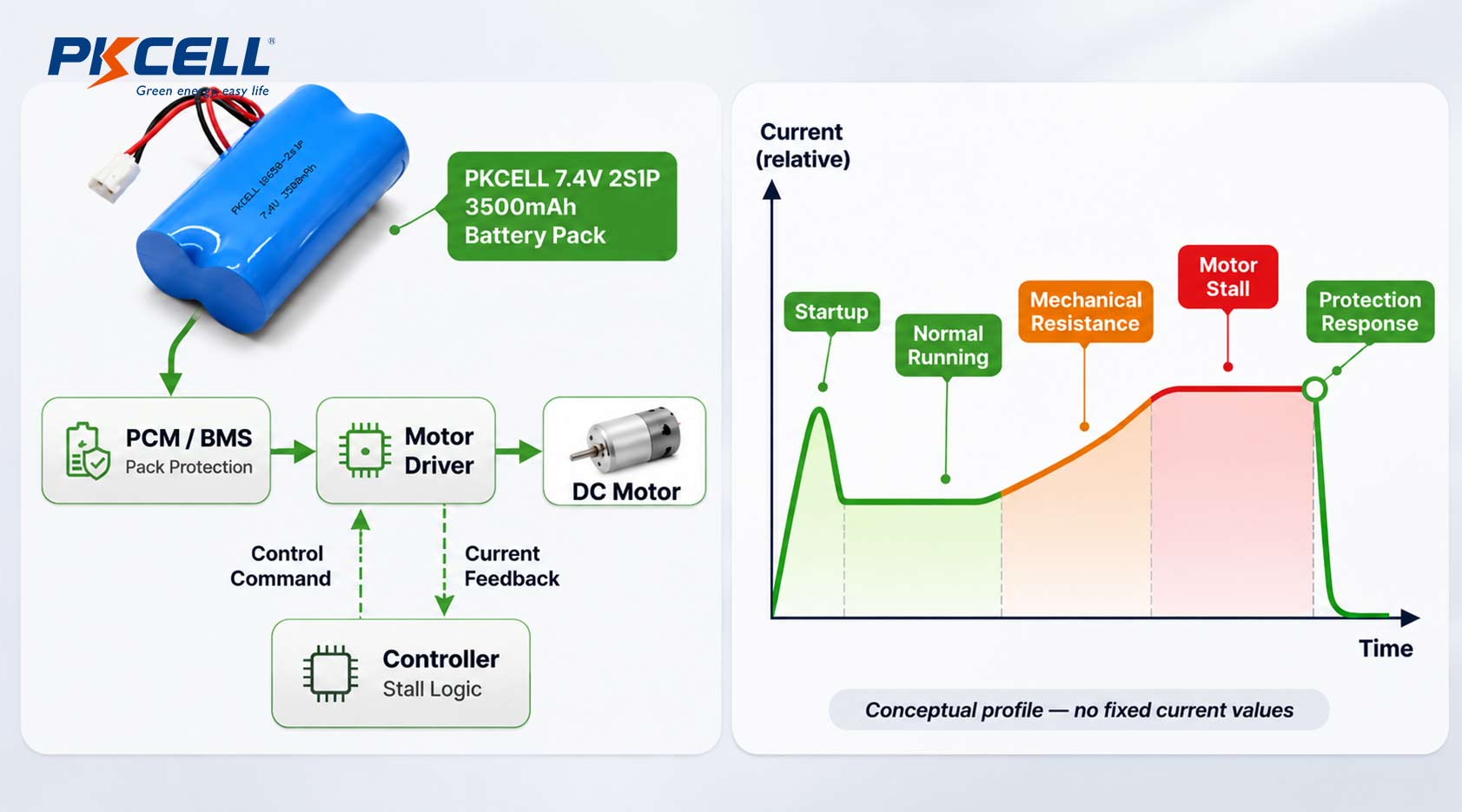
Motorized blinds experience different electrical loads during startup, normal movement and mechanical obstruction.
When the motor encounters excessive resistance or becomes blocked, its current demand may rise significantly. This can cause battery voltage sag, motor driver overheating or unnecessary BMS protection trips.
Common causes include:
- Fabric becoming trapped or misaligned.
- Excessive friction inside the roller or guide rail.
- Mechanical obstructions preventing movement.
- Incorrect motor torque or travel-limit settings.
How Should the Protection System Respond?
A reliable design should coordinate motor control and battery protection rather than relying on the BMS alone.
| Operating Condition | Required Design Response |
|---|---|
| Motor startup | Support the required starting current without unnecessary shutdown |
| Normal movement | Maintain stable voltage and current delivery |
| Mechanical obstruction | Detect abnormal loading and stop the motor |
| Battery overcurrent | Activate the specified battery protection |
| Repeated fault conditions | Prevent uncontrolled automatic restart attempts |
Three components deserve particular attention:
Motor driver: Select a driver that supports the motor’s actual startup and operating current profile, with appropriate current monitoring or limiting.
Control firmware: Use current sensing, encoder feedback or other suitable methods to identify abnormal movement and stop the motor when required.
Battery protection circuit: Specify appropriate overcurrent, short-circuit, over-discharge and temperature protection according to the battery design.
Texas Instruments discusses current monitoring for brushed DC motors in its Integrated Current Sensing application brief.
The battery output wiring and connectors must also support the expected current. See PKCELL’s guide to Battery Pack Wire Gauge: Current, Length and Voltage Drop.
3. How Can OEMs Estimate Battery Charging Intervals?
Battery capacity alone cannot accurately predict how often motorized blinds need charging. A practical estimate should include both continuous standby consumption and energy used during motor movement.
Step 1: Define the Daily Movement Profile
For a roller blind, one complete operating cycle can be defined as one upward movement and one downward movement.
OEMs should establish the expected daily movement count based on:
- Scheduled opening and closing.
- Manual remote-control operations.
- App-based adjustments.
- Sensor-triggered automation.
Step 2: Calculate Daily Energy Consumption
The simplified calculation model is:
Standby energy:
Estandby = Vbattery × Istandby × 24
Motor energy per complete cycle:
Ecycle = (Vmotor × Imotor × t) / (3600 × η)
Here, t is total motor running time in seconds and η is the motor-drive path efficiency.
If current is measured directly at the battery terminals, calculate energy using battery-side voltage and current instead; do not apply conversion efficiency a second time.
Total daily energy:
Edaily = Estandby + (N × Ecycle) + Eaccessories
Where N is the number of complete movement cycles per day.
Step 3: Estimate the Charging Interval
Usable battery energy:
Eusable = Vnominal × Capacity × Fusable × Fretention
Estimated charging interval:
Days = Eusable / Edaily
The usable energy fraction and end-of-life capacity retention should reflect the OEM’s design assumptions and validation results.
Practical Calculation Example
Consider an illustrative 7.4V rechargeable battery pack used in a motorized blind.
| Parameter | Assumed Value |
|---|---|
| Battery capacity | 2,000mAh |
| Nominal battery energy | 14.8Wh |
| Standby current | 2mA |
| Motor voltage | 7.4V |
| Average motor current | 0.8A |
| Running time per complete cycle | 20 seconds |
| Motor-drive efficiency | 90% |
| Complete cycles per day | 4 |
| Usable energy fraction | 80% |
| End-of-life capacity retention | 80% |
A. Daily standby consumption
B. Energy per complete movement cycle
C. Daily motor consumption
D. Total daily energy consumption
E. Usable battery energy
F. Estimated charging interval
In this example, standby consumption represents approximately 71% of total daily energy use.
Reducing standby current from 2mA to 0.5mA could increase the estimated interval to approximately 40 days under the same assumptions.
These figures are illustrative calculations, not guaranteed battery life. Actual performance depends on motor load, wireless activity, temperature, battery aging, cutoff voltage and installation conditions.
4. How Can High-Mounted Smart Blinds Be Designed for Convenient Charging and Maintenance?
Many motorized blinds are installed above windows or inside narrow headrails. If users must remove the complete blind assembly to recharge the battery, routine maintenance becomes inconvenient.
Charging access should therefore be considered during the initial mechanical design.
Three Practical Charging Approaches
1. Accessible Charging Port
Integrate a charging connector into an accessible section of the headrail or end cap. This allows users to recharge the battery without removing the motor assembly.
2. Magnetic Charging Connector
A magnetic connector or extension cable can simplify charging when the port is located in a narrow or difficult-to-reach position.
3. Removable Battery Module
A removable cartridge allows users or technicians to replace or recharge the battery without dismantling the complete blind system.
The design should account for connector durability, battery retention, polarity protection and repeated removal.
What Should OEMs Consider?
Before finalizing the battery compartment, review:
- Whether the charging port remains accessible after installation.
- Whether the battery can be removed without damaging the wiring.
- Whether the connector is protected against accidental disconnection.
- Whether users can identify low-battery and charging status.
- Whether battery replacement requires special tools or professional servicing.
The charging connector is only the interface. The actual charging circuit must still match the selected rechargeable battery chemistry, series configuration, voltage and current limits.
For motorized curtain and smart-home applications, see PKCELL’s Smart Home Battery Solutions.
5. How Should OEMs Validate Battery Pack, Motor Driver and Charging System Compatibility?
A battery pack should not be approved based on capacity or a standalone discharge test alone. The final product combines a rechargeable battery, motor, driver, control electronics, charging circuit and mechanical assembly.
These components must be validated together under representative operating conditions.
OEM Compatibility Validation Checklist
| Validation Area | Key Items to Verify |
|---|---|
| Battery voltage | Maximum, nominal and minimum operating voltage |
| Motor startup | Starting current and voltage stability |
| Normal movement | Current under different blind loads |
| Motor stall | Obstruction detection and shutdown response |
| Battery protection | Overcurrent, short-circuit and temperature response |
| Standby consumption | MCU, wireless module, sensors and BMS current |
| Charging compatibility | Charging voltage, current and termination |
| Mechanical integration | Battery dimensions, mounting and connector retention |
| Long-term performance | Repeated operation and battery aging |
Testing should use production-intent samples, including low-state-of-charge conditions and representative mechanical loads.
Selecting a Suitable Battery Pack Format
Depending on available space, voltage requirements and motor current, OEMs can evaluate different rechargeable battery pack configurations.
PKCELL provides several relevant product and solution categories:
- 18650 Lithium-Ion Battery Packs for cylindrical cell configurations.
- Li-Polymer Battery Solutions for compact designs requiring flexible form factors.
- Customized Battery Pack Services for project-specific voltage, capacity, wiring, connectors and protection arrangements.
The final configuration should be determined by the measured motor load, standby consumption, charging method, available installation space and maintenance requirements.
What Information Should OEMs Provide?
For a customized smart blinds battery project, prepare:
- Motor rated voltage and operating specifications.
- Startup, normal running and stall current.
- Expected daily movement cycles.
- Measured standby current.
- Battery compartment dimensions.
- Preferred charging method.
- Required runtime between charges.
- Operating temperature and estimated annual quantity.
Developing a Custom Battery Pack for Your Smart Blinds Project?
PKCELL supports rechargeable battery pack development for smart-home applications. Share your motor specifications, battery compartment dimensions, charging requirements and expected runtime to discuss a suitable battery configuration and sample evaluation.
Conclusion
Reliable battery-powered smart blinds require more than sufficient nominal capacity. Standby consumption, motor startup and stall behavior, charging access and system compatibility all influence the finished product’s performance.
For OEM manufacturers, evaluating these requirements together during product development can help reduce unnecessary charging, improve maintenance convenience and create a more reliable motorized blind system.
Post time: Nov-09-2026


