
How to Validate Spot Weld Quality in 18650 and 21700 Battery Packs
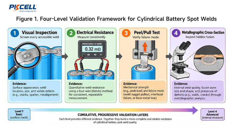
A spot weld can look clean and still have insufficient fusion, unstable electrical resistance or poor mechanical strength. It can also be too aggressive, damaging the nickel strip or the cell terminal. For 18650 and 21700 battery packs, reliable weld validation therefore requires more than visual inspection. A practical quality plan combines appearance checks, destructive peel or pull testing, electrical resistance measurement, selective cross-section analysis and ongoing process monitoring.
Why Spot Weld Quality Matters in 18650 and 21700 Packs
In a cylindrical lithium-ion battery pack, welded tabs create the electrical connection between individual cells, parallel groups, series connections, fuse elements and the BMS. A weak connection can increase local resistance, generate heat or separate under vibration. An excessively energetic weld can damage the tab or cell terminal.
The objective of the welding process is therefore not simply to create a visible electrode mark. It is to form a repeatable electrical and mechanical connection while minimizing damage to the battery cell and surrounding components.
Spot weld quality can be affected by many variables:
- Cell terminal geometry and surface condition
- Cell terminal material or coating
- Nickel or nickel-plated tab material
- Tab thickness and width
- Electrode shape and wear
- Electrode pressure
- Weld current or energy
- Pulse duration and pulse sequence
- Fixture alignment
- Contact pressure between the tab and cell terminal
- Machine calibration and power stability
Because these factors interact, a parameter that works well for one cell and tab combination should not automatically be transferred to another.
For OEM projects using cylindrical cells, PKCELL provides 18650 battery pack solutions as well as custom pack development for applications requiring different cell formats, BMS functions and structural configurations.
Start by Defining the Exact Weld Joint
Before testing weld quality, define exactly what joint is being evaluated. A result has limited value if it cannot be traced back to the cell, tab, electrode and welding parameters used to make the sample.
The positive and negative terminals of the same cylindrical cell may not behave identically during welding. Their geometry, thermal path and terminal construction may differ. For this reason, both sides should be evaluated independently when they use welded connections.
Likewise, moving from an 18650 to a 21700 cell should trigger a process review. Even when the same tab material is used, terminal geometry and heat transfer characteristics may change.
1. Visual Inspection: The First Quality Screen
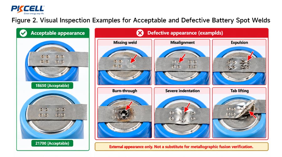
Visual inspection is the fastest method and can be applied to every accessible weld. It is useful for identifying missing welds, misalignment, excessive electrode indentation and obvious process instability.
What to Check During Visual Inspection
- All specified weld points are present.
- The welds are located in the correct area.
- Electrode impressions are reasonably consistent.
- The tab lies flat against the terminal.
- There is no obvious burn-through.
- There are no torn or cracked tab edges.
- Excessive metal expulsion or debris is absent.
- The cell terminal is not visibly pierced or severely deformed.
- The weld does not interfere with insulating rings or terminal safety features.
- No loose metallic particles remain inside the battery assembly.
2. Destructive Peel Testing
A destructive peel test provides direct evidence of how the welded interface behaves when mechanically loaded. The tab is pulled away from the cell terminal in a controlled direction, often at approximately 90 degrees to the original joint plane.
The purpose is not only to determine whether the tab separates. Engineers should also inspect where the joint fails and whether material is pulled from one of the welded surfaces.
What Failure Mode Should Be Recorded?
A stronger weld may remove a small portion of material from one side of the joint, sometimes described as material pullout or button formation. A clean separation directly along the original interface can indicate insufficient fusion or another process problem.
However, the exact acceptable failure mode depends on the joint design, tab material, cell terminal and required mechanical load. One visual failure pattern should not be treated as a universal specification for every battery weld.
Make the Peel Test Repeatable
- Use representative production cells and tabs.
- Use the same weld pattern planned for production.
- Secure the battery so it does not move during testing.
- Grip the tab without damaging the weld beforehand.
- Maintain a consistent pulling direction and approximate angle.
- Use a repeatable test speed if a force gauge or tensile tester is available.
- Record the peak force.
- Photograph the failure surface.
- Record the failure mode as well as the force result.
A single successful peel test shows that one sample survived. Process validation must demonstrate repeatability across multiple samples and normal manufacturing variation.
3. Pull, Shear and Mechanical Load Testing
A peel test concentrates stress near the edge of the weld. The finished battery pack may experience different forces during assembly, vibration, shock or long-term use.
Depending on the application, additional mechanical tests may be appropriate.
- Axial pull test: applies force away from the terminal.
- Shear test: loads the welded tab parallel to the connection surface.
- Cross-tension test: applies an opening-type load across the weld.
- Flex test: evaluates repeated movement of the tab or wire connection.
- Pack vibration test: evaluates whether welds remain intact in the final battery structure.
- Mechanical shock test: evaluates sudden loads relevant to transport or equipment use.
A mechanical-force requirement should always specify the test method. A statement such as “weld strength must exceed X newtons” is incomplete unless the pull direction, fixture and test speed are also defined.
4. Measure Electrical Resistance
A mechanically strong weld can still create unwanted electrical resistance. Measuring the resistance of the welded connection provides another important quality indicator.
Use Four-Wire Kelvin Measurement
Battery tab weld resistance is very low. A conventional two-wire multimeter can include test-lead resistance, probe contact resistance and wire resistance in the result.
A four-wire Kelvin method separates the current path from the voltage-sensing path and is more suitable for low-resistance measurements.
The measurement fixture should control probe location and contact pressure. If the probes are positioned at different distances from the weld from one sample to another, the reading may include different lengths of nickel strip or cell terminal and become difficult to compare.
Use a Qualified Baseline
Instead of relying on one generic milliohm value, establish a baseline from validated samples. Compare future production measurements with this approved distribution.
Resistance trend monitoring can help identify gradual process changes caused by electrode wear, surface contamination, altered contact pressure or material variation before a severe defect becomes obvious.
5. Metallographic Cross-Section Inspection
Cross-section inspection reveals details that cannot be seen from the outside. The welded sample is cut through the joint, mounted and polished so the interface can be inspected under magnification.
Features to Evaluate
- Fusion between the tab and terminal
- Weld nugget formation
- Penetration into the joined materials
- Incomplete or intermittent fusion
- Voids or porosity
- Cracks
- Excessive material thinning
- Excessive electrode indentation
- Consistency between repeated weld samples
Cross-sectioning is particularly valuable during initial process qualification, root-cause analysis, cell or tab material changes and investigation of unusual field failures.
It should not replace other testing. One cross-section examines only one plane through one weld, so mechanical and electrical testing remain important.
How to Establish a Stable Welding Process Window
Finding one setting that produces one acceptable sample is not enough. The objective of process development is to identify a stable range of settings that consistently creates acceptable welds despite normal production variation.
Step 1: Fix the Joint Configuration
Define the exact cell model, terminal side, tab material, tab thickness, electrode geometry, fixture and weld pattern before comparing welding parameters.
Step 2: Test a Parameter Matrix
Evaluate combinations of welding current or energy, pulse duration, pulse sequence and electrode force. Development samples should cover under-welded, acceptable and over-welded conditions so the practical process boundaries become visible.
Step 3: Apply Multiple Validation Methods
Perform visual inspection, destructive testing and resistance measurement on representative samples. Cross-section selected conditions around the proposed production window.
Step 4: Challenge Normal Manufacturing Variation
Repeat the process using different representative material lots, normal electrode wear and expected equipment variation. Positive-terminal and negative-terminal welds should be considered separately when their structures differ.
Step 5: Select a Production Setting Inside the Stable Region
The preferred production condition should normally be located inside the demonstrated process window rather than directly beside an under-weld or over-weld boundary.
| Process Variable | If Too Low or Poorly Controlled | If Excessive | Useful Validation Method |
|---|---|---|---|
| Weld current or energy | Weak fusion and high joint resistance | Expulsion, burn-through or terminal damage | Peel test, resistance and cross-section |
| Pulse duration | Insufficient heat generation | Excessive heat input and indentation | Visual inspection and cross-section |
| Electrode force | Unstable contact and possible expulsion | Changed interface resistance or excessive deformation | Force verification and destructive test |
| Electrode condition | Changing contact area can alter current density | Severe wear can reduce process consistency | Tip inspection and trend monitoring |
| Part fit-up | Gaps and poor contact cause unstable current flow | Excessive fixture force may deform components | Fixture inspection and destructive verification |
| Surface condition | Oil, oxidation or debris can change interface resistance | Not normally an excessive setting issue | Incoming material inspection and resistance trends |
Production Controls After Welding Qualification
Initial qualification shows that the selected process can produce acceptable welds. Production control verifies that the same process remains stable during actual manufacturing.
- Lock or control access to the approved welding program.
- Verify machine calibration according to a defined schedule.
- Check electrode force at defined intervals.
- Control the position of cells and tabs using repeatable fixtures.
- Inspect first-off samples before starting a production batch.
- Define electrode-cleaning and replacement rules.
- Repeat validation after significant electrode maintenance.
- Monitor welding current, voltage, energy, power or displacement when equipment supports it.
- Use periodic destructive samples based on product and process risk.
- Inspect critical welds before insulation or the final enclosure hides them.
- Maintain traceability to welding machine, parameter program, cell lot and tab lot.
What In-Process Weld Monitoring Can Do
Modern resistance welders can record parameters such as current, voltage, energy, power and electrode displacement. These signals can help detect abnormal weld conditions in real time.
For example, a sudden change in resistance or energy profile may indicate poor tab contact, contamination, electrode wear or a missing component.
However, weld-monitor data becomes useful only after it has been correlated with actual weld quality. The approved machine signature should be established using samples that have already passed mechanical, electrical and, where required, metallographic testing.
In-process monitoring is most valuable for controlling a previously validated process. It should not be treated as a complete replacement for destructive verification.
18650 vs. 21700: Can the Same Weld Settings Be Used?
Not automatically. The validation methods are similar, but the welding schedule can change between 18650 and 21700 cells.
Different cells may use different terminal geometry, surface coatings, material thicknesses and internal structures. Even cells with the same nominal size can behave differently if they come from different manufacturers or product series.
The welding process should be reviewed when any of the following changes:
- 18650 cells are replaced by 21700 cells.
- The cell manufacturer changes.
- The exact cell model changes.
- The tab material changes.
- The tab thickness changes.
- The tab width changes significantly.
- The weld-point location or pattern changes.
- The welder or power supply changes.
- The electrode material or tip geometry changes.
- A busbar, fuse wire or multilayer conductor is introduced.
OEM teams considering larger cylindrical cells can review PKCELL’s 21700 rechargeable battery options together with available 18650 rechargeable battery models before finalizing the pack structure.
Spot Weld Quality and Battery Pack Current
Spot weld requirements should also reflect the electrical load of the finished battery pack. A connection that appears adequate in a low-current device may become a heating point in a high-current pack if its resistance is excessive.
The weld should therefore be considered together with the conductor cross-section, series and parallel arrangement, continuous current, peak current and thermal environment.
For customized packs, PKCELL can evaluate cell configuration, conductor arrangement, BMS, connector and pack structure through its custom battery pack service.
Common Battery Spot Weld Validation Mistakes
- Approving weld quality based only on appearance.
- Testing only one weld sample.
- Performing an uncontrolled hand-pull test with no defined direction.
- Recording pull force without documenting the failure mode.
- Using a normal two-wire multimeter for very low joint resistance.
- Using inconsistent resistance probe positions.
- Transferring welding settings from one cell model to another without validation.
- Ignoring electrode wear.
- Changing the tab thickness without repeating process checks.
- Inspecting welds only after insulation or the housing has hidden them.
- Assuming a repeatable machine automatically produces an acceptable weld.
- Failing to document cell and material lot traceability.
Recommended Spot Weld Validation Record
A complete weld-validation report should provide enough information for the process to be repeated and audited.
- Cell manufacturer and exact cell model
- 18650 or 21700 cell format
- Positive and negative terminal identification
- Tab material and thickness
- Joint drawing and weld-point locations
- Welding machine identification
- Electrode specification
- Fixture identification
- Welding current or energy setting
- Pulse time and pulse sequence
- Electrode force
- Visual acceptance reference photographs
- Peel or pull test method
- Mechanical test data
- Failure-mode photographs
- Electrical resistance test method and results
- Cross-section photographs where required
- Sample quantity
- Material-lot traceability
- Approved parameter range
- Production verification frequency
- Conditions requiring requalification
When Should Spot Welding Be Revalidated?
Revalidation should be considered whenever a change could alter current flow, pressure, heat generation or joint geometry.
Typical triggers include a new cell supplier, different tab alloy, different tab thickness, welding-machine replacement, electrode redesign, fixture changes, major equipment maintenance or repeated production failures.
Routine verification should also be performed after significant electrode replacement or dressing because the electrode contact area directly affects current density at the weld.
Information to Send for a Custom 18650 or 21700 Pack
If you are developing a custom cylindrical battery pack, providing the following information helps the battery supplier evaluate both the electrical architecture and the manufacturing process.
- Required pack voltage
- Required capacity
- Preferred 18650 or 21700 cell
- Continuous discharge current
- Peak discharge current and duration
- Charging current
- Series and parallel configuration if defined
- Available pack dimensions
- BMS protection requirements
- Connector and wire specifications
- Operating temperature range
- Vibration or mechanical shock requirements
- Required certifications
- Target sales markets
- Estimated annual quantity
You can submit these specifications through the PKCELL contact page for project review.
Frequently Asked Questions
How can you tell if an 18650 spot weld is good?
A reliable evaluation should combine visual inspection with a controlled mechanical test such as peel or pull testing. For higher-confidence validation, low-resistance measurement and selected metallographic cross-sections can also be used.
Is a visible spot weld mark enough to prove weld quality?
No. A normal electrode impression can exist even when fusion at the hidden interface is weak. Visual inspection is useful for screening obvious defects but should not be the only validation method.
What is a battery tab peel test?
A peel test pulls the welded tab away from the cell terminal in a controlled direction, often at approximately 90 degrees. Engineers record the required force and inspect how the joint fails.
Can a normal multimeter measure battery spot weld resistance?
A standard two-wire multimeter is generally not ideal for characterizing very low weld resistance because lead and contact resistance can affect the reading. A four-wire Kelvin measurement method is more appropriate.
Can 18650 and 21700 cells use the same spot welding settings?
They should not be assumed to use identical settings. Terminal construction, material, coating, geometry and thermal behavior can differ. Each important cell-and-tab combination should be validated.
How often should battery spot welds be destructively tested?
The frequency should be defined by the production control plan and can depend on product risk, manufacturing volume, process capability and customer requirements. Additional testing may be required after electrode replacement, parameter changes, material changes or abnormal production results.
Does weld monitoring replace peel testing?
No. Process-monitoring data can identify drift or abnormal signatures, but the limits should first be correlated with actual weld quality. Periodic destructive verification helps confirm that this relationship remains valid.
Conclusion
Spot weld quality in 18650 and 21700 battery packs should be validated as a manufacturing process rather than judged by appearance alone. Visual inspection can identify obvious defects, peel and pull testing provide mechanical evidence, four-wire resistance measurement evaluates the electrical path, and cross-section analysis can reveal hidden fusion quality.
Once a stable welding window has been qualified, production controls should monitor machine settings, electrode condition, fixtures, material lots and periodic destructive test results.
Revalidation is particularly important when changing cell models, tab materials, electrode geometry or welding equipment. A welding schedule proven for one battery configuration should not automatically be assumed suitable for another.
Need a Custom 18650 or 21700 Battery Pack?
Send PKCELL your required voltage, capacity, continuous and peak current, battery dimensions, cell preference, BMS functions, connector, mechanical environment and forecast quantity. The engineering team can review the cell configuration and pack manufacturing requirements for your OEM project.
Post time: Oct-08-2026


