
How to Select a Battery Connector for an OEM Device
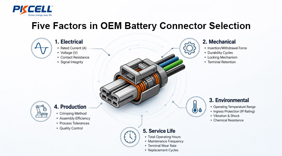
The connector on a custom battery pack is a small component with system-level consequences. A poor choice can create excessive voltage drop, local heating, intermittent resets, reversed polarity, difficult assembly, water ingress, or field-service failures. Selecting the right battery connector for an OEM device therefore requires more than matching the plug shape and nominal current printed in a catalog.
Start with the Connector’s Real Job
First define whether the connection is permanent, factory-mated, user-removable, or frequently serviced. A connector hidden inside a sealed product may only be mated during assembly and repair. A removable battery interface may experience hundreds or thousands of cycles, blind mating, contamination, and user misalignment. These are different engineering problems.
Document every circuit passing through the interface:
- Battery positive and negative power contacts
- Charging contacts, if charge and discharge paths are separate
- NTC thermistor or temperature-sense lines
- Battery identification or presence-detection contacts
- SMBus, I²C, CAN, UART, or other communication lines
- Enable, wake, authentication, or ground-first contacts
PKCELL can customize the connector, wiring, NTC, protection circuit, label, and pack structure as part of an OEM battery pack development project. Defining the complete interface early prevents the connector from becoming a late mechanical compromise.
Calculate Current from the Worst-Case Load
Do not select a connector from average device current. Use measured or verified continuous current, repetitive pulse current, motor or capacitor inrush, startup duration, charging current, and credible fault current. Include low battery voltage because a constant-power device may draw more current as pack voltage falls.
Connector current ratings are conditional. They may depend on ambient temperature, acceptable temperature rise, conductor size, contact plating, number of simultaneously loaded contacts, enclosure airflow, and test method. A catalog value marked “up to” is not automatically the allowable current in the OEM device.
Check each part of the current path
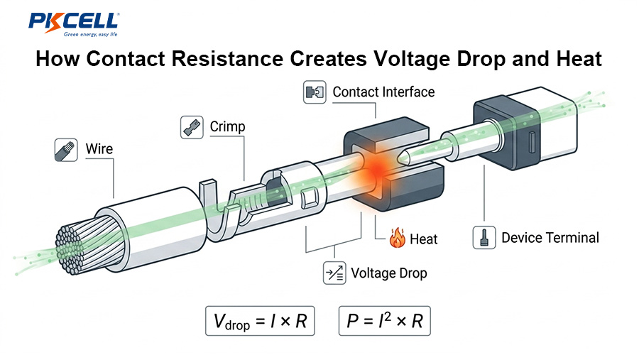
The power interface includes the crimp, contact pair, housing, PCB header or panel receptacle, solder joint, wire, and strain relief. The permissible pack current is limited by the weakest element. If multiple contacts are paralleled for power, verify that the manufacturer permits it and that current sharing remains acceptable despite contact-resistance variation.
Control Contact Resistance, Voltage Drop, and Heat
Every connection adds resistance. Even a low value matters when current is high, especially after vibration, contamination, fretting, wear, or an imperfect crimp increases resistance. Connector losses reduce the voltage available to the device and create localized heat near plastic housings and battery wiring.
Evaluate the maximum specified resistance, not only the initial typical value. The validation plan should measure millivolt drop and terminal temperature after thermal cycling, vibration, mating durability, and environmental exposure relevant to the product.
Match the Connector to the Wire and Termination
The selected terminal must accept the required conductor cross-section and insulation diameter. Wire ampacity alone is not enough: a cable that is too large or too small for the terminal can produce an unreliable crimp. Confirm conductor material, strand construction, insulation type, strip length, crimp height, pull-force requirement, and approved application tooling.
- Crimp termination: usually preferred for repeatable volume production when approved terminals and tooling are available.
- Solder termination: may suit certain low-volume designs, but solder wicking and inadequate strain relief can create a rigid fatigue point.
- PCB termination: requires review of pin current, copper area, solder-joint temperature, mechanical load, and board support.
- Spring or blade contacts: useful for removable batteries but sensitive to alignment, surface wear, contact force, and contamination.
Also review total cable length and device voltage tolerance. A suitable connector cannot compensate for an undersized wire harness. PKCELL’s battery technology and BMS capabilities can be considered together with the connector, fuse, NTC, and harness design.
Choose Pin Count, Polarity, and Contact Sequence
A two-pin connector may be sufficient for a simple protected pack, while a smart battery can require power, temperature, communication, presence, and enable contacts. Keep high-current paths appropriately separated from sensitive signals and confirm that the housing provides adequate voltage spacing for the application.
Mechanical keying should prevent reversed polarity and mating with an incompatible pack. Color alone is not reliable poka-yoke. For interfaces that mate while powered, investigate whether the application needs staggered contacts, first-make/last-break behavior, pre-charge, current limiting, or a separate enable signal. Never assume a connector is suitable for hot plugging unless the selected series and system have been evaluated for it.
Select the Right Locking and Mating Method
Friction locks can work in light-duty internal assemblies. Positive latches, secondary locks, bayonet couplings, threaded shells, or lever locks may be needed when vibration, cable pull, frequent handling, or safety consequences are higher. The retention force must resist service loads without making assembly ergonomically difficult.
| Connection type | Typical advantage | Main questions to verify |
|---|---|---|
| Wire-to-board latch | Compact and production-friendly inside devices | PCB support, cable routing, latch access, current per contact |
| Wire-to-wire lock | Flexible harness assembly and service replacement | Retention, strain relief, keying, exposed-contact protection |
| Sealed automotive-style connector | Resistance to moisture, dust, and vibration | Seal compatibility, backshell, crimp process, mated IP rating |
| Blade or spring-contact interface | Convenient removable or docked battery | Alignment, wipe length, contact force, wear, cleaning, touch safety |
| Circular or threaded connector | Robust coupling and many contact arrangements | Size, weight, torque, mating time, coding, environmental rating |
Account for Mating Cycles and Service Life
Mating durability varies widely among connector families. An internal connector rated for a few dozen operations is not equivalent to a docking connector designed for thousands of cycles. Define how often production, testing, customer use, maintenance, and repair will mate the interface, then add an appropriate service-life margin.
Do not interpret the cycle rating in isolation. Check the conditions of the durability test and the post-test electrical requirements. Contact plating, wipe action, insertion alignment, cleaning agents, dust, and whether mating occurs under load can all influence real life.
Design for Temperature, Vibration, and Ingress
Connector temperature rating must cover ambient temperature plus self-heating and nearby cell or electronics heat. At low temperature, cable and latch materials may stiffen. At high temperature, plastics, seals, and contact force can degrade. Confirm chemical compatibility with adhesives, potting materials, cleaning agents, oils, and other fluids in the product environment.
For humid, outdoor, medical-cleaning, industrial, or vehicle applications, determine whether sealing is required and whether the published IP rating applies only when fully mated with the correct seal, wire size, backshell, and unused-cavity plugs. A sealed housing does not automatically prevent condensation inside the battery enclosure.
Vibration testing should use the final wire length, routing, tie-down points, strain relief, and mounting arrangement. A connector that survives as a free component may still fail when the cable applies leverage to the housing.
Balance Size with Assembly and Safety
The smallest connector is not always the best connector. Very tight pitch can reduce keying options, strain-relief space, creepage distance, finger access, and assembly robustness. Ask whether operators can fully seat the connector, visually or electrically confirm locking, avoid pin damage, and remove it with the intended tool during service.
For compact portable products, explore PKCELL’s consumer electronics battery solutions, which include customization of pack dimensions, wires, connectors, NTCs, and protection designs.
A Practical Selection Matrix
| Selection parameter | Required input | Evidence to request | Prototype verification |
|---|---|---|---|
| Current and voltage | Continuous, pulse, inrush, charging, and fault cases | Connector derating data and applicable specifications | Voltage drop and temperature rise at worst case |
| Wire termination | Wire gauge, strand, insulation diameter, and material | Approved terminal, crimp specification, and tooling | Crimp dimensions, pull force, microsection if required |
| Mechanical retention | Vibration, shock, cable pull, and service access | Latch and terminal-retention requirements | Pull, vibration, shock, and inspection |
| Environment | Temperature, humidity, water, dust, fluids, and altitude | Temperature and sealed-system ratings | Environmental exposure followed by electrical tests |
| Mating life | Production, use, and repair cycle count | Durability rating and post-cycle limits | Cycle test followed by resistance and retention checks |
| Supply and production | Annual volume, geography, lead time, and automation needs | Lifecycle status, authorized sources, and tooling availability | Pilot-run capability and process-control review |
Validate the Complete Battery Interface
Measure voltage drop, contact resistance, temperature rise, insulation resistance, and fault response.
Test terminal retention, latch retention, cable pull, misalignment, vibration, shock, and drop.
Apply relevant hot, cold, humidity, condensation, dust, water, corrosion, and fluid exposures.
Run the required mating cycles and recheck resistance, retention, housing damage, and plating wear.
Verify crimp settings, terminal insertion, secondary locks, polarity, pinout, and end-of-line tests.
Test low-SOC peaks, startup, charging, hot plugging where permitted, intermittent faults, and safe shutdown.
Approve a connector by its performance as a finished battery-cable-device interface, not by the appearance of a catalog sample.
Common OEM Connector Selection Mistakes
- Selecting from average current instead of worst-case and low-voltage current
- Using the headline current rating without checking wire size and temperature-rise conditions
- Ignoring contact resistance growth after vibration and mating cycles
- Choosing identical unkeyed connectors for incompatible voltage or polarity interfaces
- Assuming the housing IP rating applies without the correct seals and cable construction
- Using a service connector with insufficient mating-cycle life
- Changing the terminal, plating, wire, or crimp tool without revalidation
- Failing to define approved manufacturer part numbers and alternates on production drawings
What to Include in a Battery Connector RFQ
For a fast engineering review and useful bulk quotation, send the following information through the PKCELL battery inquiry page:
- Battery chemistry, nominal voltage, capacity, and series/parallel configuration
- Continuous, peak, inrush, charging, and fault-current requirements
- Connector manufacturer and part number, if already specified
- Pinout, polarity, communication, NTC, ID, and enable requirements
- Wire gauge, length, color, insulation, exit direction, and strain relief
- Mechanical drawings, available mating space, latch access, and cable routing
- Operating environment, mating-cycle target, and device validation plan
- Destination market, certification needs, sample quantity, annual forecast, and schedule
Frequently Asked Questions
How much current margin should an OEM battery connector have?
There is no universal percentage. Select from the worst-case current and verify the manufacturer’s derating conditions, maximum contact resistance, wire size, ambient temperature, loaded-contact count, enclosure conditions, and required life. Confirm the margin with temperature-rise and voltage-drop tests.
Can two connector pins be paralleled to carry more current?
Only when the connector manufacturer permits the arrangement and the design controls current sharing. Differences in contact resistance, mating sequence, crimp quality, and PCB routing can overload one contact. Validate each path and the failure of a single contact.
Should a removable battery connector be hot-pluggable?
Not unless the connector and complete circuit are designed and validated for live mating. Inrush, arcing, contact sequencing, pre-charge, protection timing, and exposed-contact safety must all be considered.
Is an IP67 connector automatically waterproof in the finished device?
No. The rating normally depends on the complete mated system, correct seals, compatible wire diameters, cavity plugs, assembly quality, and specified test conditions. Enclosure leakage and condensation require separate evaluation.
Which connector details should appear on the battery pack drawing?
Specify manufacturer, complete part number, mating half, terminal, plating, wire gauge and insulation, pinout, polarity, wire length and tolerance, crimp requirement, cable exit, strain relief, labels, approved alternates, and inspection criteria.
Can PKCELL customize battery connectors and wiring?
Yes. PKCELL supports custom wire length, gauge, connector, pinout, NTC, label, PCM/BMS, casing, and pack structure subject to engineering review and validation. Existing device drawings or mating-connector samples help avoid compatibility errors.
Which certifications can PKCELL support for an OEM battery project?
PKCELL lists ISO 9001 and ISO 14001 management systems and product-related certifications or reports including UL 1642, CB/IEC 62133, CE, RoHS, REACH, UN 38.3, MSDS, KC, PSE, and UKCA across its portfolio. Exact coverage depends on the selected cell, pack configuration, connector interface, destination market, and project scope. Confirm the applicable route using the PKCELL certification overview.
What production capacity is available for volume projects?
PKCELL publicly reports a 28,000 m² manufacturing base, more than 20 automated production lines, over 400 team members, and annual battery production capacity of up to 500 million units. Capacity for a specific connectorized pack depends on cell supply, harness complexity, test time, forecast stability, and approved line allocation.
What information is needed for a bulk price quotation?
Provide the pack voltage and capacity, load profile, connector and terminal part numbers, pinout, wire specification, cable length, BMS functions, enclosure, compliance markets, sample quantity, annual volume, delivery schedule, packaging, and test requirements. Include drawings and the mating-device interface whenever possible.
What are the MOQ and sample options?
Prototype samples can be discussed for fit, electrical, and device testing. PKCELL product pages indicate that formal orders may start from a total value of about USD 500, but the actual custom-pack MOQ depends on cells, connector availability, tooling, electronics, certification, and packaging. Request project-specific sample and production terms.
What connector quality records should an OEM buyer request?
Agree on approved part numbers, incoming inspection, crimp-height and pull-force checks, terminal insertion and secondary-lock verification, polarity and pinout testing, electrical end-of-line limits, lot traceability, tooling maintenance, nonconformance control, and engineering change approval.
Conclusion
The best battery connector is not simply the smallest model that fits or the one with a sufficient headline current rating. It is the interface that carries the real current with acceptable voltage drop and heat, prevents incorrect mating, survives the product environment and service life, supports controlled manufacturing, and remains available throughout the OEM program. Define these requirements with the pack, cable, device, and validation plan as one system.
Need a Connector-Ready Custom Battery Pack?
Share your device pinout, load profile, mating connector, wire requirements, mechanical drawing, target certifications, and annual forecast. PKCELL can review the interface and prepare a project-specific sample and bulk quotation.
Post time: Aug-17-2026


