
OEM Battery Pack Engineering Guide
How to Read a Lithium-Ion Cell Datasheet for OEM Design
A lithium-ion cell datasheet can tell you whether a cell is a plausible candidate for an OEM battery pack. It cannot, by itself, prove that the finished pack will meet runtime, power, life, safety, and certification targets. The real engineering task is to read every headline number together with its test conditions, limits, and effect at pack level.
Start with chemistry and form factor, then verify minimum capacity, voltage limits, continuous current, charge method, temperature range, impedance, cycle-life conditions, dimensions, and safety notes. Convert those cell-level values into series/parallel pack requirements, add realistic electrical and thermal margins, and validate the result with representative loads before freezing the design.
This guide gives OEM engineers, sourcing teams, and product managers a practical sequence for reading a lithium-ion cell datasheet. It also explains which specifications are commonly misunderstood and what information a battery pack manufacturer will still need before recommending a cell.
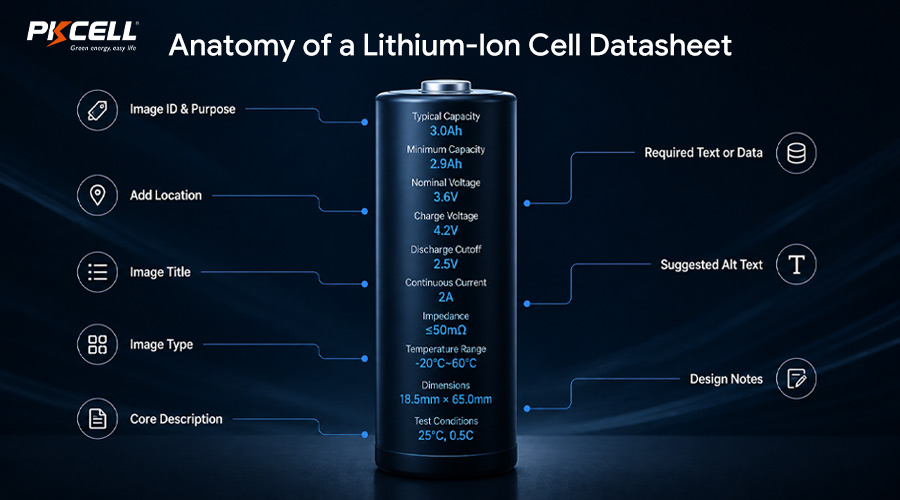
First, Identify Exactly What the Datasheet Covers
Confirm the manufacturer, model number, revision, and publication date before comparing numbers. A family name is not enough: two cells with the same diameter and length may have different chemistry, capacity, current capability, terminals, or permitted applications.
Also check whether you are reading a product datasheet, a detailed cell specification, a safety data sheet, or a pack specification. These documents serve different purposes. A one-page product sheet may be useful for screening, but it may not include the charge-current derating, pulse conditions, storage limits, or warnings needed for design approval.
- Model and revision: Make sure the quoted cell and the tested cell match the document.
- Cell format: Cylindrical, prismatic, and pouch cells impose different mechanical and thermal constraints.
- Chemistry: Labels such as ICR, INR, or NCA may provide a useful clue, but the manufacturer’s stated limits remain authoritative.
- Qualification status: Ask whether the exact production cell, configuration, and supplier are covered by the relevant reports.
If your project is still choosing a cylindrical format, PKCELL’s 21700 vs. 18650 battery comparison is a useful first-pass reference. Format alone does not determine performance, so return to the exact model datasheet before making the final selection.
Read Capacity and Energy Without Overestimating Runtime
Typical capacity is not a production guarantee
Datasheets often show both typical capacity and minimum capacity. Typical capacity describes a representative result under stated laboratory conditions. Minimum capacity is the more conservative value for a design calculation and supplier acceptance criteria.
For example, Molicel’s INR-21700-P42A product datasheet lists 4,200 mAh typical and 4,000 mAh minimum capacity. It also states the charge and discharge conditions used to generate its curves. That difference matters: a pack designed around the typical value may miss its runtime target even before aging, cold temperature, voltage-conversion losses, and cell-to-cell variation are considered.
Energy in watt-hours is usually more useful than amp-hours when comparing cells with different nominal voltages. For a pack with cells in series and parallel:
This result is a nominal starting point, not guaranteed usable energy. The device cutoff, BMS thresholds, load profile, cell voltage sag, temperature, conversion efficiency, and aging reserve all reduce what the product can actually use.
OEM rule of thumb: size runtime from minimum capacity under the closest available test condition, then validate usable pack energy under the real duty cycle.
Check the capacity test conditions
Before transferring a capacity value into your design spreadsheet, find the test temperature, charge method, rest period, discharge current, and cutoff voltage. A capacity measured at room temperature and a gentle discharge rate will not predict the same runtime at low temperature, under a high load, or with an earlier system cutoff.
Translate Cell Voltage Into the Pack Voltage Window
A datasheet may show nominal voltage, charge voltage, and discharge cutoff voltage. Each has a different job:
- Nominal voltage is a reference value for energy and pack labeling. It is not the cell’s constant operating voltage.
- Maximum charge voltage determines charger regulation and informs BMS overcharge protection design.
- Discharge cutoff voltage is the test or absolute discharge endpoint stated by the cell maker. It is not automatically the best product-level cutoff.
For a 4S pack using 4.2 V maximum-charge cells, the charger regulates the series string to 16.8 V. The BMS protection thresholds, device undervoltage behavior, charger accuracy, balancing strategy, and component voltage ratings must all be coordinated around the complete operating window.
Separate Continuous Current, Pulse Current, and C-Rate
Current ratings are among the most frequently misread cell specifications. A continuous-discharge rating may depend on temperature limits, cooling, cell orientation, and the manufacturer’s end-of-discharge criteria. A pulse rating is meaningless unless the datasheet defines pulse duration, rest time, state of charge, and temperature.
C-rate expresses current relative to capacity. For a 4 Ah cell, 1C equals 4 A. However, C-rate does not make two different cells thermally equivalent. Internal resistance and cell construction determine how much voltage sag and heat each cell produces.
A 30 A load on a 3P pack ideally divides to 10 A per cell. Real current sharing can be uneven because of cell impedance variation, interconnect geometry, temperature gradients, weld resistance, and aging. The pack therefore needs design margin and a current-path layout that promotes balanced sharing.
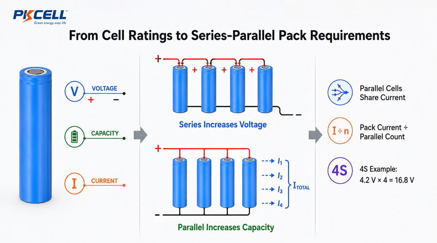
Lithium-Ion Cell Datasheet Checklist for OEM Teams
| Datasheet field | What to verify | Pack-level consequence | Common mistake |
|---|---|---|---|
| Typical and minimum capacity | Test rate, temperature, cutoff, and revision | Runtime, energy, parallel count, acceptance limits | Designing only to the typical value |
| Nominal and limit voltages | Charge voltage and discharge endpoint | Series count, charger, BMS, component ratings | Treating nominal voltage as a fixed output |
| Charge current | Standard, maximum, termination, and temperature | Charge time, heat, charger power, pack life | Using maximum charge current as the default |
| Discharge current | Continuous versus pulse conditions and thermal limits | Parallel count, busbars, connector, BMS, cooling | Multiplying a headline rating without derating |
| AC/DC impedance | Method, frequency, state of charge, and temperature | Voltage sag, heat generation, current sharing | Comparing values measured by different methods |
| Temperature ranges | Separate charging, discharging, and storage limits | Thermistors, heaters, cooling, firmware interlocks | Assuming discharge range also permits charging |
| Cycle life | Retention threshold, C-rates, DOD, temperature, rests | Warranty model and replacement interval | Quoting cycle count without its test protocol |
| Dimensions and weight | Maximum dimensions, tolerances, sleeve, terminals | Cell holders, compression, enclosure, logistics | Designing the enclosure to nominal size |
Need help turning a cell datasheet into a pack specification?
Send PKCELL your load profile, target runtime, available space, operating temperature, charging requirements, connector details, and target certifications. The engineering team can review cell selection, S/P configuration, protection, and prototype requirements.
Do Not Ignore Impedance, Voltage Sag, and Heat
Internal resistance or impedance influences both delivered voltage and heat generation. Datasheets may report AC impedance at 1 kHz, DC resistance under a short current pulse, or both. Those numbers cannot be compared directly because the methods are different.
These simplified relationships show why a modest increase in current can cause a much larger thermal burden. They also explain why maximum current is not simply a BMS setting. Cell temperature, enclosure airflow, spacing, thermal interfaces, busbar resistance, connector loss, and neighboring heat sources affect the safe pack current.
Use datasheet curves to compare candidates, then build a thermal model and test instrumented prototypes. Record cell temperatures at likely hot spots, terminal voltage at peak load, BMS temperature, connector temperature, and recovery after repeated duty cycles.
Read Charging Requirements as a Complete Protocol
Lithium-ion cells commonly use constant-current/constant-voltage charging, but the complete recipe matters. Check charge voltage, standard and maximum current, CV termination current, permitted charge temperature, and any time limit. The charger and BMS perform related but different functions: the charger regulates the normal profile, while the BMS provides monitoring and protection.
A faster permitted charge rate does not mean it is best for every product. Faster charging may increase heat, require more capable power electronics, and reduce the design margin available at cold or hot temperatures. If field life matters more than the shortest possible charge time, evaluate a lower normal charge rate and reserve faster charging for controlled conditions.
PKCELL’s custom battery pack service covers pack structure, wires, connectors, protection circuits, and application-specific battery design. These details need to be aligned with the cell’s charge specification rather than added after cell selection.
Interpret Temperature Ratings Carefully
Datasheets normally specify separate temperature ranges for charging and discharging. The charge range is often narrower. A cell that can deliver current below 0 degrees C may still require charging to be blocked, reduced, or managed with a qualified low-temperature strategy.
Temperature limits are boundaries, not proof of equal performance across the range. At low temperature, available capacity and power may fall while voltage sag rises. At high temperature, short-term performance can look strong even as degradation and safety risk increase. Define both ambient temperature and the cell temperature expected inside the enclosure.
- Place NTC sensors where testing identifies credible hot and cold spots.
- Define charge and discharge derating in BMS or host firmware.
- Test cold start, sustained load, charging after discharge, and solar or vehicle heat soak when relevant.
- Include aging and blocked-vent scenarios in the thermal review.
Cycle-Life Graphs Are Test Results, Not a Universal Lifetime Promise
A cycle-life claim is incomplete without charge rate, discharge rate, depth of discharge, temperature, rest periods, cutoff voltages, and end-of-life definition. If the graph ends at 80% capacity retention, it does not mean the cell suddenly fails at that point. It means capacity under that test has reached the stated threshold.
Calendar aging also matters. A low-cycle product can still lose capacity while stored, especially at high temperature and high state of charge. For warranty planning, build a use-case model that includes daily cycles, partial cycling, time at high SOC, storage periods, thermal exposure, and expected peak loads.
Mechanical Dimensions: Design to the Maximum, Not the Name
Terms such as 18650 and 21700 describe a format, not a complete mechanical tolerance. Use the datasheet’s maximum diameter and height, then account for the insulating washer, sleeve, terminal geometry, cell holder, nickel or copper interconnects, weld features, assembly tolerances, swelling where applicable, vibration restraint, electrical clearances, and service strategy.
The enclosure must also manage venting without turning a vent path into an ignition path toward the user or critical electronics. Mechanical integration therefore belongs in the early cell-selection process, not after electrical sizing.
To review available formats and example configurations, see PKCELL’s rechargeable battery product range and custom lithium-ion battery pack options.
A Practical OEM Workflow: From Datasheet to Approved Pack
- Freeze the product requirements. Document average and peak power, pulse duration, runtime, voltage window, charging source, physical envelope, ambient conditions, product life, and compliance markets.
- Screen multiple cell candidates. Compare minimum capacity, current capability, impedance, temperature performance, dimensions, sourcing stability, and application restrictions under equivalent conditions.
- Choose a preliminary S/P configuration. Calculate the voltage range, minimum beginning-of-life energy, per-cell current, charge current, and expected loss budget.
- Apply design margins. Account for cell variation, aging, temperature, uneven current sharing, electronics consumption, converter efficiency, cutoff headroom, and transient loads.
- Co-design the pack. Select the BMS, protection thresholds, fuse strategy, balancing, conductors, connector, temperature sensing, enclosure, spacing, and thermal path as one system.
- Build representative prototypes. Use production-intent cells, interconnects, BMS hardware, charger, enclosure, and firmware wherever possible.
- Validate worst cases. Test maximum load, minimum and maximum temperature, low and high SOC, repeated pulses, abnormal charging, aging, and realistic mechanical stress.
- Control the production configuration. Lock the exact cell model and revision, approved suppliers, incoming inspection, traceability, firmware, drawings, test limits, and change-notification process.
OEM projects that need end-to-end support can review PKCELL’s consumer electronics battery engineering capabilities, including cell selection, BMS and structural design, prototyping, testing, and certification support.
Common Datasheet Reading Mistakes
- Comparing capacities at different discharge rates or cutoffs. Normalize the test conditions first.
- Using typical capacity as guaranteed pack output. Start with minimum capacity and subtract system losses and reserves.
- Treating a maximum rating as a normal operating point. Continuous production designs need margin.
- Assuming pulse current means any pulse. Require a defined pulse duration, rest interval, SOC, and temperature.
- Ignoring voltage sag at the device cutoff. A cell can retain energy that the system cannot access under load.
- Multiplying cell current by parallel count without checking the current path. Unequal resistance and temperature can unbalance current sharing.
- Comparing AC impedance with DC resistance. Keep the measurement method and conditions consistent.
- Assuming a cell certificate automatically covers the pack. Confirm the exact compliance route for the finished product, battery, and shipment.
- Designing around one cell with no change-control plan. Supply continuity and qualification of changes are OEM requirements too.
What to Send a Battery Pack Manufacturer
A clear engineering brief produces a more useful recommendation than simply asking for a certain amp-hour rating. Include:
- Product application and target markets
- Continuous, peak, and pulse load profiles
- Required runtime and acceptable end-of-life runtime
- System input-voltage range and device cutoff behavior
- Available space, mounting method, and weight target
- Charge source, desired charge time, and use-during-charge behavior
- Operating, charging, and storage temperatures
- Connector, wire, communication, fuel-gauge, and NTC requirements
- Expected annual volume, prototype quantity, and launch schedule
- Required safety, transport, and market certifications
Frequently Asked Questions
Should OEM pack capacity be calculated from typical or minimum cell capacity?
Use minimum cell capacity as the conservative beginning-of-life basis, then account for temperature, load, conversion losses, cutoff behavior, cell variation, and aging. Verify usable energy with the actual pack and device load.
Can I multiply the cell’s maximum discharge current by the parallel count?
That result is only a screening calculation. The finished pack may be limited by cell temperature, current imbalance, interconnects, connector, fuse, BMS, enclosure, or application duty cycle. Apply margin and validate the assembled pack.
What is the difference between nominal voltage and charge voltage?
Nominal voltage is a reference used for identification and energy calculations. Charge voltage is the upper regulation target specified by the cell maker. Charger and BMS values must be designed around the full cell and pack voltage window.
Why does measured runtime differ from the datasheet capacity?
The datasheet result is tied to stated laboratory conditions. Real runtime changes with current, temperature, voltage sag, device cutoff, converter efficiency, electronics consumption, cell variation, and age.
Is a cell datasheet enough to approve an OEM battery pack?
No. Pack approval also requires electrical, thermal, mechanical, protection, charger, firmware, manufacturing, traceability, abuse, transportation, and product-compliance review. Testing should use representative production-intent hardware.
Conclusion: Treat the Datasheet as the Start of the Design
A strong OEM battery pack begins with disciplined interpretation. Read the exact cell revision, compare minimum values under matching conditions, translate voltage and current to the complete S/P configuration, and evaluate temperature, impedance, aging, mechanics, and protection together. Then verify the design with representative prototypes and a controlled production specification.
Turn Your Product Requirements Into a Custom Battery Pack
Share your voltage range, load profile, runtime target, enclosure space, temperature range, charger, connector, expected volume, and certification needs with PKCELL. Our team can help evaluate cell options and develop an OEM battery pack for prototype and production.
Post time: Aug-06-2026


