
How to Define Safety Margins for Custom Battery Packs
A custom battery pack should not be designed to operate continuously at the edge of a cell, component, or protection-device rating. Real products face cold starts, hot enclosures, current spikes, cell variation, sensor error, aging, charger tolerance, and manufacturing variation. Custom battery pack safety margins create controlled distance between those real-world conditions and the limits that can shorten life or trigger a hazardous failure.
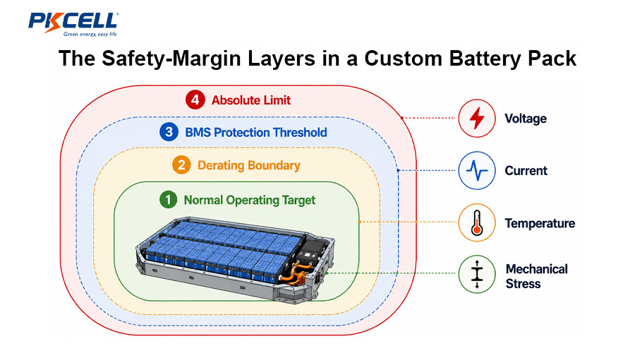
What a Battery Pack Safety Margin Actually Means
A safety margin is the engineered separation between expected operating stress and a limiting condition. It is not automatically “20% extra capacity” or “use a larger fuse.” Each parameter needs its own definition because upper limits, lower limits, transient limits, and lifetime limits behave differently.
- Normal operating target: the region expected during routine use.
- Control or derating boundary: the point where the system reduces charge power, output power, or another stress.
- Protection threshold: the BMS or independent protection point that stops the condition after an appropriate delay.
- Absolute limit: the cell or component boundary that must not be reached in the validated design.
For a lower limit, reverse the relationship. More importantly, the “worst case” must include measurement error, tolerance, thermal lag, imbalance, degradation, and dynamic overshoot. The required margin is therefore a result of risk analysis and evidence, not a universal percentage.
Start with a Worst-Case Requirements Envelope
Before selecting cells or programming a BMS, translate the application into operating cases. A medical cart, handheld scanner, industrial sensor, and high-power robot may use similar lithium-ion cells but need very different margins. Review the application with an experienced custom battery pack manufacturer early enough to change the architecture.
- Maximum continuous, pulse, startup, regenerative, and fault current
- Minimum and maximum charger or adapter voltage, including tolerance and transients
- Ambient, cell, enclosure, and charging-temperature ranges
- Load duration, duty cycle, rest periods, and repeated peak events
- Required runtime at beginning and end of life
- Cell-to-cell spread, production tolerance, and aging divergence
- Altitude, humidity, vibration, shock, ingress, and cooling restrictions
- Single-fault cases and foreseeable misuse defined by the product risk assessment
A defensible margin links a requirement to a known limit, includes uncertainty, and has a test that proves it remains intact.
Voltage Margins: Charge, Discharge, and Transients
Upper charge-voltage margin
Do not place the charger regulation point, BMS overvoltage threshold, and cell upper limit at the same value. Allow for charger accuracy, BMS measurement error, resistor tolerance, balancing overshoot, wiring drop, cell imbalance, and switching transients. The BMS threshold must protect the cell without causing nuisance trips during compliant charging.
Lower discharge-voltage margin
Loaded cell voltage falls as current and internal resistance increase. Cold temperature and aging make that sag worse. A cutoff chosen only from a room-temperature, low-current datasheet test can produce resets, weak runtime, or cell undervoltage in the field. Model the weakest cell under the highest credible load and allow for protection delay.
Component voltage derating
MOSFETs, capacitors, protection ICs, connectors, and insulation systems need ratings above the maximum credible steady-state and transient voltage. Pack series count alone is not enough; inductive loads and hot-plug events can produce brief but damaging spikes. PKCELL’s overview of battery management and pack technology explains how cell monitoring and protection fit into the wider design.
Current and Power Margins
Separate continuous current, repetitive pulse current, short-duration peak current, inrush current, and fault current. Each creates a different thermal and electrical stress. In an ideal parallel group, cell current is pack current divided by the parallel count, but real current sharing is affected by cell impedance, interconnect resistance, temperature, weld consistency, and state of charge.
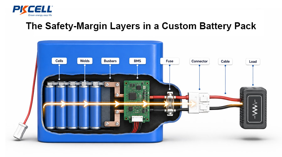
The usable pack current is limited by the weakest part of the path: cells, busbars, nickel or copper conductors, welds, PCB traces, MOSFETs, shunt, fuse, connector, cable, and thermal interface. Since resistive heating rises with the square of current, a modest current increase can create a much larger heat increase.
Thermal Margins and Sensor Uncertainty
Temperature limits should protect the hottest cell during discharge and the coldest cell during charging. An NTC measures its installation point, not every cell. Add margin for sensor tolerance, ADC error, thermal gradients, adhesive and insulation effects, sensor response time, control-loop delay, and temperature rise after current is reduced.
Use thermal mapping to find hot and cold locations at low, nominal, and high ambient temperature. Repeat testing after aging or with cells representing higher internal resistance. For temperature-sensitive applications such as medical battery solutions, define sensor plausibility checks and the system response to an open or shorted thermistor.
Capacity, Energy, and Runtime Margins
Begin with minimum qualified cell capacity rather than a typical marketing value. Then account for temperature, load rate, voltage cutoff, conversion efficiency, BMS standby consumption, production spread, calendar aging, cycle aging, and the reserve required by the user experience. A fuel-gauge learning value should represent the application conditions rather than simply copying a datasheet capacity.
Capacity reserve is not a substitute for current capability. A large-energy cell can still be unsuitable if its impedance, charge acceptance, or thermal behavior cannot support the duty cycle. Compare available battery chemistries and product formats against the complete load profile.
Component, Mechanical, and Environmental Margins
Electrical margins only work when the mechanical design preserves them. Include cell dimensional tolerance, swelling allowance where relevant, enclosure deflection, vibration movement, weld and busbar tolerance, insulation compression, vent paths, creepage and clearance, gasket compression, condensation paths, and cooling-channel variation.
- Wires and connectors: verify ampacity, voltage drop, contact resistance, mating cycles, and terminal temperature.
- Protection hardware: derate FETs, fuses, shunts, capacitors, and PCB copper for temperature and tolerance.
- Insulation: retain dielectric strength after assembly, abrasion, vibration, and contamination.
- Enclosure: protect cells without trapping unacceptable heat or blocking necessary pressure relief.
- Ingress controls: consider water, dust, humidity, pressure change, and internal condensation as separate mechanisms.
Coordinate Protection Thresholds and Delays
A BMS setting is a protection layer, not the complete safety case. Thresholds and delays should include monitor-IC tolerance, sense-network tolerance, temperature drift, filter delay, switching time, fault-current rise, and the safe operating area of the disconnect devices. Primary electronic protection, secondary protection, and a fuse should be coordinated so each layer acts within its validated capability.
For a deeper system-level starting point, see PKCELL’s guide to custom battery pack design principles.
A Practical Safety-Margin Worksheet
| Parameter | Define the worst case | Add uncertainty | Set control and protection | Validation evidence |
|---|---|---|---|---|
| Cell charge voltage | Highest charger output and most imbalanced group | Measurement, resistor, balancing, and transient error | Charge control below protection; protection below the qualified limit | Corner-unit charge and fault tests |
| Cell discharge voltage | Weakest aged cell at cold temperature and peak load | Voltage sag, monitor error, and delay | Power derating before undervoltage shutdown | Cold, aged-cell, and pulse-load tests |
| Pack current | Continuous, repetitive pulse, inrush, and stalled-load cases | Sharing error, resistance spread, and component tolerance | Application limit, BMS limit, and fuse coordination | Temperature-rise and protection-trip tests |
| Cell temperature | Hottest discharge cell and coldest charging cell | Sensor error, gradient, lag, and overshoot | Derating before protective shutdown | Instrumented thermal mapping |
| Runtime | End-of-life duty cycle at limiting temperature | Capacity spread, conversion loss, and standby load | Low-SOC warning and shutdown reserve | Representative load-profile testing |
| Mechanical stress | Worst shock, vibration, swelling, and enclosure tolerance | Production and material variation | Structural restraint without cell damage | Environmental and post-test inspection |
A Seven-Step Design Workflow
- Capture the real duty cycle. Measure startup, steady, pulse, sleep, charging, and abnormal states.
- Select candidate cells and components. Use qualified limits, minimum values, and temperature-dependent data.
- Calculate corner cases. Combine credible tolerances, aging, imbalance, voltage drop, thermal rise, and transients.
- Assign layered boundaries. Document normal targets, derating points, BMS thresholds, delays, and absolute limits.
- Perform design risk analysis. Connect each hazard and failure mode to prevention, detection, and mitigation controls.
- Prototype and validate. Test cold, hot, aged, imbalanced, low-SOC, peak-load, charger-fault, and environmental cases.
- Lock production controls. Freeze approved parts, programming, test limits, traceability, and change-control rules.
Common Safety-Margin Mistakes
- Applying one blanket percentage to voltage, current, temperature, and runtime
- Using typical cell values instead of minimum, maximum, and tolerance data
- Treating a short pulse-current rating as a repetitive system operating point
- Ignoring cold-temperature impedance and low-SOC voltage sag
- Placing a single temperature sensor where it cannot detect the thermal extreme
- Programming BMS thresholds before characterizing measurement accuracy and delay
- Validating only fresh, balanced packs at room temperature
- Changing cells, firmware, weld settings, or enclosure materials without re-evaluating the margins
What to Include in a Custom Pack RFQ
A detailed RFQ lets the engineering team assess margins before quoting tooling and production. For an OEM lithium battery pack, provide:
- Nominal voltage, allowable voltage range, runtime, and energy target
- Continuous, peak, pulse-duration, inrush, and fault-current data
- Charge source, charge time, interface, and expected use while charging
- Operating, storage, and charging-temperature ranges
- Mechanical envelope, connector, wire length, enclosure, and ingress needs
- Target life, annual demand, forecast ramp, sample quantity, and launch schedule
- Destination markets and required transport, safety, and environmental compliance
- Available load profiles, CAD files, risk requirements, and host communication protocol
Send these details through the PKCELL battery project inquiry form so the initial review can focus on design feasibility and the evidence needed for a reliable quotation.
Frequently Asked Questions
How much safety margin should a custom battery pack have?
There is no universal percentage. The margin depends on cell chemistry, load profile, environment, measurement accuracy, aging target, failure severity, and applicable requirements. Define and validate a separate margin for each critical parameter.
Should the charger limit and BMS overvoltage threshold be identical?
No. The charger should regulate normal operation, while the BMS threshold is a protection boundary. Their separation must accommodate accuracy, balancing behavior, cell variation, transients, and protection response without exceeding the qualified cell limit.
Can the cell’s maximum discharge-current rating be used as the pack’s continuous rating?
Not automatically. Pack current may be limited by temperature, parallel-group sharing, welds, busbars, BMS FETs, PCB copper, fuses, connectors, wires, enclosure cooling, or the application’s required life.
How should aging be included in the margin?
Use an end-of-life capacity and resistance target, then test or model the pack at the limiting temperature, state of charge, and load. Higher aged-cell resistance affects voltage sag, heat, power capability, and cell-to-cell balance.
Is a BMS enough to make a custom battery pack safe?
No. The BMS is one layer. Cell selection, mechanical restraint, insulation, thermal design, charger behavior, fusing, software, manufacturing controls, product-level risk management, and validation all contribute to safety.
Which authoritative certifications can PKCELL support?
PKCELL lists ISO 9001 and ISO 14001 management systems and certifications or reports including UL 1642, CB/IEC 62133, CE, RoHS, REACH, UN 38.3, MSDS, KC, PSE, and UKCA across its product portfolio. Exact applicability depends on the chosen cell, finished-pack configuration, destination market, and project scope. Buyers should confirm the required certification path and sample plan before tooling; see the PKCELL certificates overview.
What factory capacity is available for volume orders?
PKCELL publicly reports a 28,000 m² manufacturing base, more than 20 automated production lines, a team of over 400 people, and annual battery production capacity of up to 500 million units. Capacity for a specific custom pack still depends on cell supply, assembly complexity, test time, forecast stability, and approved line allocation.
What information is required for an accurate bulk quotation?
Provide voltage, energy or capacity, continuous and peak current, pulse duration, temperature range, dimensions, connector and cable details, BMS functions, communication protocol, compliance markets, annual forecast, order schedule, packaging, and validation requirements. Drawings and a measured load profile improve quote accuracy.
What are the MOQ and sample options?
Samples can be discussed for design verification. PKCELL product pages indicate that formal orders may start from a total value of about USD 500, but the actual MOQ for a custom pack varies with cell availability, custom tooling, electronics, certification, and packaging. Request project-specific sample and mass-production terms.
Can PKCELL customize safety margins and BMS thresholds?
Yes, where supported by the selected protection platform and validated design. The settings should be based on qualified cell limits, application corner cases, component tolerances, and the required compliance path, then controlled through approved firmware and production test records.
What quality records should a volume buyer request?
Agree on incoming-cell controls, lot traceability, cell matching criteria, weld and assembly controls, BMS programming verification, end-of-line test limits, reliability validation, nonconformance handling, and engineering change control. Project-specific inspection reports and traceability requirements should be defined in the quality agreement.
Conclusion
Good safety margins are visible, traceable, and testable. They come from the gap between a realistic worst-case operating envelope and qualified limits after tolerances, aging, temperature, transients, and faults have been included. When these boundaries are coordinated across the cell, BMS, power path, thermal system, enclosure, and production process, the result is a pack that is more reliable in the field and easier to validate for volume production.
Define Your Battery Pack Margins Before Tooling
Share your load profile, operating environment, mechanical limits, target market, and annual forecast. PKCELL can review the requirements and prepare a project-specific custom battery pack proposal and bulk quotation.
Post time: Aug-17-2026


