
Dashcam Battery Pack Design Guide: Parking Mode, Heat, Low-Voltage Cutoff & Charging
A reliable dashcam battery pack must do more than keep a camera running after the ignition is switched off. It has to support the required parking duration, recharge during realistic journeys, tolerate a hot vehicle cabin, protect the starter battery, and deliver stable power through every engine start and voltage transient. This guide explains how OEMs and product teams can turn those requirements into a practical battery specification.
1. Choose the Dashcam Parking-Mode Power Architecture
A hardwired dashcam can draw energy directly from the vehicle’s starter battery, from a dedicated auxiliary battery pack, or from a system that combines both. The right architecture depends on parking duration, camera power, driving frequency, available installation space, climate, and acceptable risk to vehicle starting.
| Architecture | Main advantage | Main limitation | Best fit |
|---|---|---|---|
| Starter battery plus hardwire kit | Low cost and simple installation | Parking operation consumes energy needed to start the vehicle | Short parking periods and regular driving |
| Dedicated dashcam battery pack | Separates surveillance energy from the starter battery | Adds cost, packaging, charging, and thermal-design requirements | Frequent or extended parking surveillance |
| Auxiliary pack with controlled vehicle cutoff | Supports longer recording while protecting both power sources | Requires coordinated controls and system-level validation | OEM, fleet, and premium multi-camera systems |
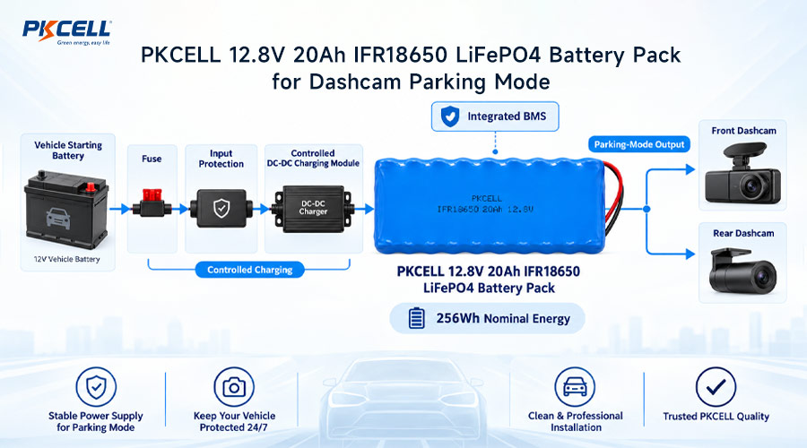
Parking mode is not automatically a very low-power state. Depending on the camera, it may use continuous low-bitrate recording, time-lapse recording, buffered motion detection, impact-triggered wake-up, or a combination of these functions. Rear cameras, LTE modules, Wi-Fi, GPS, and cloud uploads can materially change the energy budget.
For example, BlackVue documents both time-lapse and motion-detection parking modes, together with voltage and timer-based battery protection. Garmin likewise notes that its parking features require constant power and are not necessarily low-power modes. The lesson for designers is straightforward: obtain a measured load profile from the exact camera configuration.
When is a dedicated battery pack worth considering?
A dedicated pack becomes more attractive when the application has one or more of these conditions:
- Parking surveillance must continue overnight or through a full workday.
- The vehicle makes short trips that provide limited recharge time.
- The system includes front and rear cameras, cellular connectivity, or cloud uploads.
- Cold-weather starting reserve is a priority.
- The vehicle may remain parked for several days.
- The product is intended for fleet or commercial use with predictable availability targets.
2. Calculate Battery Capacity from Real Parking-Mode Energy
Battery capacity should be calculated in watt-hours rather than chosen from an amp-hour label alone. Watt-hours make it possible to compare packs with different nominal voltages and account for the conversion stage between the battery and the dashcam.
Suppose a two-channel dashcam averages 4.5 W in its selected parking mode and must operate for 18 hours. If the power path is 85% efficient and the design allows 80% of nominal pack energy to be used:
At a nominal 12.8 V, that example corresponds to approximately 9.3 Ah. This is an illustrative engineering estimate, not a universal dashcam specification. The final capacity must be based on measured power, cell data, BMS consumption, cable losses, temperature, aging, and the customer’s runtime target.
Use a complete load profile
A single current reading can hide important events. Measure average and peak consumption during continuous recording, motion analysis, impact wake-up, file writing, LTE transmission, Wi-Fi use, and startup. Also measure the pack’s own standby consumption and the quiescent current of the DC-DC converter.
A battery that meets the nominal watt-hour calculation can still miss the runtime target if cold-temperature capacity loss, conversion losses, BMS consumption, or end-of-life degradation is ignored.
Build margin deliberately
Capacity margin should account for:
- Cell capacity tolerance and production variation
- Reduced usable energy at temperature extremes
- Capacity fade and higher internal resistance at end of life
- Converter, wiring, connector, and protection-device losses
- Camera firmware updates that may alter power consumption
- Occasional high-activity periods with frequent event recording
There is no universal safety-margin percentage. PKCELL’s guide to
custom battery pack safety margins
explains why limits should be derived from the real operating envelope, tolerances, aging targets, and failure consequences.
3. Design for Heat Inside a Parked Vehicle
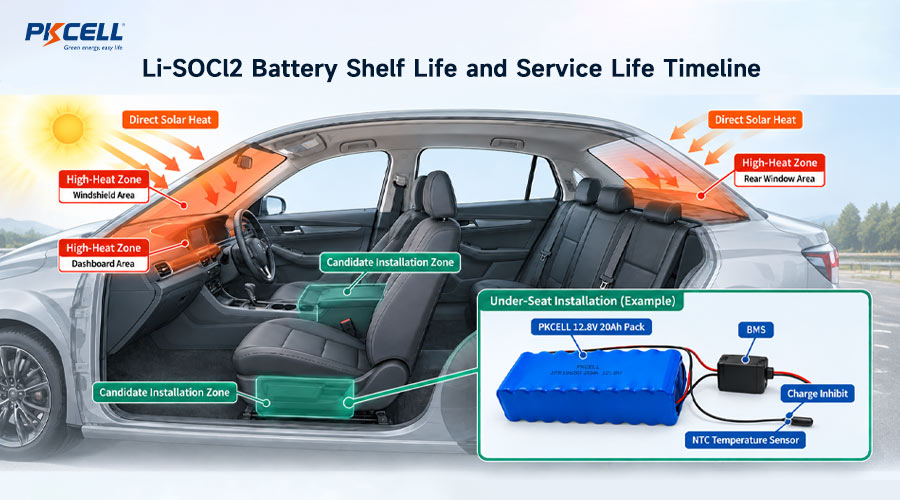
Temperature is often the defining constraint for a dashcam battery pack. A vehicle parked in direct sunlight can be much hotter inside than the outdoor air. A published vehicle-temperature study found cabin temperatures could exceed ambient temperature by more than 20°C, while vehicle color and solar exposure also affected the result.
This means an outdoor forecast of 35°C does not describe the battery’s actual environment. The pack may be exposed to a much higher local temperature near the windshield, dashboard, roof liner, or other sun-heated surface.
Cell chemistry helps, but does not replace thermal engineering
LiFePO4 is frequently considered for auxiliary dashcam power because of its thermal and chemical stability, cycle-life potential, and useful power capability. However, a chemistry label alone does not qualify a pack for installation in a hot car. Designers must use the approved temperature limits of the exact cell model and evaluate the complete pack.
Review PKCELL’s
LiFePO4 battery pack options
when comparing voltage, capacity, cell format, and custom-pack possibilities for parking surveillance equipment.
Separate operating, charging, and storage limits
A battery may have different permitted temperatures for discharge, charge, and storage. Charging is commonly the more restrictive condition. The BMS should therefore be capable of preventing or reducing charging when measured cell temperature is outside the cell manufacturer’s qualified range.
- Charge over-temperature: inhibit charging before the cell limit is reached.
- Charge under-temperature: block or restrict charging where required by the selected chemistry and cell specification.
- Discharge over-temperature: disconnect or derate the output before unsafe heating develops.
- Temperature recovery: apply appropriate hysteresis so the system does not repeatedly switch on and off near a threshold.
- Sensor fault: define safe behavior for an open, shorted, detached, or implausible temperature sensor.
Installation location is part of the electrical specification
Avoid treating pack placement as a final packaging decision. A position near the windshield may experience a different temperature from a ventilated location under a seat or within a protected console. Compare candidate locations using instrumented vehicles, including worst-case solar exposure and post-drive heat soak.
The enclosure should support heat spreading without trapping unnecessary heat around the cells, BMS MOSFETs, charger, and converter. Thermal interface materials, sensor placement, cell spacing, venting strategy, cable routing, and nearby heat sources should all be reviewed together.
4. Coordinate Low-Voltage Cutoff at Two Different Levels
“Low-voltage cutoff” can refer to two separate functions, and confusing them creates a serious design gap.
| Protection layer | What it monitors | Primary purpose |
|---|---|---|
| Vehicle-input cutoff | Starter-battery or vehicle-supply voltage | Preserve enough vehicle-battery reserve for reliable starting |
| Pack undervoltage protection | Auxiliary pack and individual series cell groups | Prevent excessive discharge of the rechargeable cells |
A pack-level BMS cutoff does not automatically protect the vehicle’s starter battery. Likewise, a hardwire kit’s vehicle-voltage cutoff does not replace cell-level monitoring inside a lithium battery pack.
As one real-world reference, BlackVue documents a 12.0 V default cutoff for passenger vehicles and 23.2 V for heavy vehicles on supported systems. These figures should not be copied blindly. The suitable setting depends on battery chemistry and condition, ambient temperature, required cranking reserve, measurement accuracy, wiring voltage drop, parasitic loads, and vehicle manufacturer requirements.
A robust cutoff strategy should define more than a threshold
- Trip voltage and measurement location
- Voltage-sensing accuracy across temperature
- Qualification delay for brief transients
- Recovery voltage and hysteresis
- Maximum parking timer
- Behavior after the vehicle supply recovers
- User notification or diagnostic logging
- Fail-safe response to disconnected sense wiring
For systems using both a voltage cutoff and a parking timer, define which condition has priority. A conservative design normally stops parking operation when the first protective limit is reached.
5. Engineer Charging Around Real Driving Patterns
The battery must not only provide enough parking energy; it must also recover that energy during the time the vehicle is driven. A large battery paired with a weak charging path can accumulate an energy deficit day after day.
For example, a 60 W charge input operating for one hour at 85% overall efficiency returns approximately 51 Wh. If the dashcam consumed 81 Wh while parked, the system begins the next parking period with an energy deficit unless there is a longer drive, a higher qualified charge rate, or an alternative charging source.
Charging-system questions to resolve
- Will power come from an accessory socket, fuse panel, USB-C source, or vehicle-integrated DC-DC stage?
- What voltage range and transients can appear at the selected input?
- How much current can the circuit, fuse, connector, and wiring safely support?
- How quickly must the battery recover after the target parking period?
- Can the dashcam operate while the pack is charging?
- How will charging change at high and low cell temperatures?
- How will the system behave during ignition-off transition and engine cranking?
Use a chemistry-matched charger
The charger profile, maximum voltage, termination behavior, and current limits must match the selected chemistry and series-cell configuration. Charging control should manage normal operation; the BMS overvoltage threshold should remain a protection boundary rather than the normal method of ending every charge.
Direct connection of a lithium pack to an automotive supply without a properly designed charging and protection stage is not an acceptable charging strategy. Automotive inputs may require protection against reverse polarity, overcurrent, surges, abnormal supply conditions, and conducted interference.
6. Specify the BMS, Power Path, and Interfaces as One System
A dashcam battery BMS should be selected from the complete operating profile, not simply from nominal capacity. PKCELL’s
custom battery pack engineering
covers cell selection, capacity, BMS functions, connectors, housing, and temperature-related requirements for application-specific packs.
Core BMS functions
- Cell-level overvoltage and undervoltage protection
- Charge and discharge overcurrent protection
- Short-circuit protection
- Charge and discharge temperature protection
- Cell balancing for series configurations
- State-of-charge estimation appropriate to the application
- Low standby current during extended parking
- Controlled recovery after a protection event
Do not overlook the power path
The cells may be capable of the required current while another component becomes the real limitation. Check the current and temperature performance of the BMS MOSFETs, PCB copper, nickel or busbar connections, fuse, connector, cable, charger, and DC-DC converter.
Startup behavior deserves special attention. If the camera has a high inrush current, the pack voltage may momentarily sag and trigger an undersized BMS. Increasing a protection threshold or delay simply to suppress nuisance trips can remove necessary protection. Investigate the load, cell impedance, interconnect resistance, and converter behavior first.
For broader architecture guidance, see PKCELL’s article on
custom battery pack design principles.
7. Validate the Battery Pack in the Actual Vehicle Environment
Cell certificates and bench tests are necessary inputs, but they do not prove that the installed dashcam system will meet its runtime, temperature, charging, electromagnetic, and vehicle-protection goals.
Recommended validation checklist
- Measure all camera operating modes and peak loads.
- Verify runtime at beginning of life and the defined end-of-life condition.
- Test hot-cabin operation, solar heat soak, and hot charging.
- Test cold parking, cold startup, and charge inhibition where applicable.
- Verify vehicle-battery cutoff accuracy at the installed sensing point.
- Test timer and voltage cutoff interaction.
- Measure cable and connector temperature at maximum charge current.
- Check behavior during engine cranking, ignition transitions, and interrupted charging.
- Verify abnormal-condition responses, including sensor faults and short circuits.
- Evaluate vibration, mounting retention, abrasion, and connector security.
- Confirm transport and target-market compliance for the final pack configuration.
Plan compliance before tooling
Compliance depends on the finished product, target market, transport method, and installation architecture. UN 38.3 addresses lithium-cell and battery transport testing; it is not a substitute for product-level safety and vehicle integration validation. Requirements such as IEC 62133-2 may also be relevant depending on how the pack is classified and marketed.
Confirm the applicable standards, reports, labels, sample quantities, and change-control process before freezing the enclosure or production tooling. Changing cells, protection electronics, or pack construction later can affect the compliance path.
What to Include in a Dashcam Battery Pack RFQ
A useful request for quotation should include more than voltage and capacity. Send the engineering team:
- Dashcam model and number of camera channels
- Measured average and peak current in every operating mode
- Required parking runtime and daily driving pattern
- Vehicle type and 12 V or 24 V electrical system
- Charging-source voltage, current limit, and connection method
- Minimum and maximum operating, charging, and storage temperatures
- Available pack dimensions, mounting location, and orientation
- Connector, cable length, pinout, and communication requirements
- Target service life, annual volume, destination markets, and certifications
Discuss Your Custom Dashcam Battery Pack
PKCELL can review your camera load profile, parking-runtime target, charging window, thermal environment, enclosure limits, BMS functions, and compliance needs to develop a project-specific battery proposal.
Frequently Asked Questions
What battery chemistry is best for a dashcam parking-mode battery?
There is no universal answer. LiFePO4 is often evaluated because of its thermal stability and cycle-life characteristics, while other lithium-ion formats may offer different energy-density or packaging advantages. The decision must be based on the exact cell’s qualified temperatures, capacity, charge rate, service-life target, available space, and complete safety architecture.
How large should a dashcam battery pack be?
Multiply measured average parking power by the required hours, then account for DC conversion efficiency, usable depth of discharge, temperature, aging, and pack standby consumption. A watt-hour calculation is more reliable than selecting a pack from amp-hours alone.
Does a dashcam’s low-voltage cutoff protect a lithium auxiliary pack?
Not necessarily. A dashcam or hardwire kit may monitor the vehicle battery, while the auxiliary pack needs its own cell-level BMS protection. The two cutoff systems protect different batteries and must be coordinated.
Can a dashcam battery charge while powering the camera?
It can if the charger and power-path architecture are designed for simultaneous charging and load operation. The design must ensure correct charge termination, thermal control, current allocation, state-of-charge estimation, and uninterrupted camera power.
Is UN 38.3 enough for a finished dashcam battery product?
No. UN 38.3 concerns transport testing for lithium cells and batteries. Product safety, electrical integration, electromagnetic compatibility, installation, and market-specific requirements must be assessed separately.
Conclusion
Successful dashcam battery pack design is an energy, thermal, charging, and vehicle-integration problem. Start with a measured parking-mode load, translate the target runtime into watt-hours, and verify that normal driving can restore the consumed energy. Then coordinate vehicle low-voltage cutoff with cell-level BMS protection and validate every operating mode at realistic temperatures.
Product teams that define these requirements before selecting cells or tooling an enclosure are better positioned to achieve dependable parking surveillance without sacrificing starter-battery reserve or battery life. To turn your requirements into a manufacturable specification,
send your dashcam battery requirements to PKCELL.
Post time: Sep-22-2026


