
OEM Battery Pack Engineering Guide
Battery Pack Wire Gauge: Current, Length & Voltage Drop
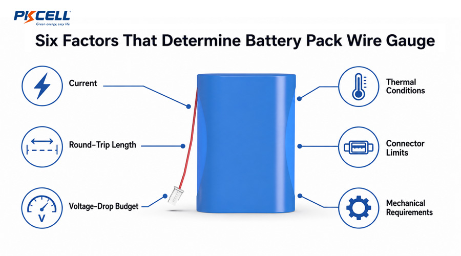
Battery pack wire gauge affects more than whether a cable can carry current. It also determines voltage delivered to the device, wiring heat, peak-load performance, connector compatibility, mechanical flexibility, and the amount of usable energy available before the system reaches its cutoff voltage.
Select battery pack wire gauge by checking both thermal capacity and voltage drop. Use the maximum realistic continuous current for temperature-rise analysis, the worst-case pulse current for transient voltage-drop analysis, and the complete round-trip conductor length. Then verify insulation temperature, ambient conditions, bundling, duty cycle, connector and terminal ratings, fuse coordination, flexibility, and production-intent test results.
Choosing wire from a generic ampacity chart alone can produce a pack that technically carries current but still fails in the product. A long or undersized cable can cause brownouts, weak motor starts, inaccurate low-voltage cutoff behavior, wasted energy, or excessive localized heat. This guide provides a practical process for OEM battery pack wire selection without treating any AWG size as a universal current rating.
What Does AWG Mean in Battery Pack Wiring?
American Wire Gauge (AWG) is a conductor sizing system. A lower AWG number represents a larger conductor. For the same conductor material and length, a larger cross-sectional area has lower electrical resistance.
AWG does not, by itself, define the complete cable. Two wires with the same gauge can use different conductor materials, strand counts, plating, insulation thicknesses, temperature ratings, outer diameters, and flexibility. These differences can affect resistance, crimp compatibility, routing, durability, and allowable operating temperature.
- Conductor gauge: Influences resistance and current density.
- Conductor material: Copper, tinned copper, and other materials may have different resistance and environmental performance.
- Stranding: Fine-stranded wire can improve flexibility but must match the selected terminal and crimp process.
- Insulation: Determines temperature, voltage, abrasion, chemical, and dimensional characteristics.
- Finished cable diameter: Must fit the enclosure, strain relief, grommet, connector housing, and assembly process.
Choose the complete wire specification, not only an AWG number.
The Three Core Inputs: Current, Length, and Voltage Drop
1. Define continuous and peak current separately
Continuous current drives sustained conductor temperature rise. Peak or pulse current may create the largest temporary voltage drop. An OEM load profile should include normal current, maximum continuous current, startup or motor-stall current, pulse magnitude, pulse duration, repetition rate, and expected simultaneous loads.
Do not automatically size the cable to the BMS overcurrent trip value. That protection threshold may be substantially higher than the normal load and may include a time delay. Wire, connector, terminal, fuse, BMS, and load requirements need coordinated ratings based on their actual functions.
High-power applications may also need a cell and pack configuration designed for the same duty cycle. PKCELL’s high-rate lithium-ion battery solutions provide context for projects where cell discharge capability, wiring, protection, and thermal design must be developed together.
2. Measure the complete current path
For a conventional two-wire DC output, current travels from the battery to the load and returns through the other conductor. Voltage-drop calculations therefore use the total conductor length, not only the one-way distance.
If both conductors have the same gauge and length, the loop length is twice the one-way distance. Include intentional cable extensions and realistic internal routing. Do not count only the straight-line distance between the battery and device.
3. Set an application-specific voltage-drop budget
The acceptable drop depends on pack voltage, device tolerance, BMS cutoff, transient behavior, and performance target. A loss that appears small in volts can be significant in a low-voltage system.
Allocate the total system budget across cell sag, BMS resistance, fuse, wiring, connectors, switches, PCB traces, and other current-path elements. A wire-only target is useful, but the load experiences the sum of every voltage loss in the path.
How to Calculate Battery Cable Resistance and Power Loss
Wire resistance is determined by the conductor specification and its length. When the manufacturer provides resistance per meter or per foot, the basic calculations are:
Resistance increases as copper temperature rises, so a room-temperature table is a starting point rather than a guarantee of hot-condition performance. Production calculations should use the wire manufacturer’s maximum resistance data and an appropriate temperature correction or validated hot test.
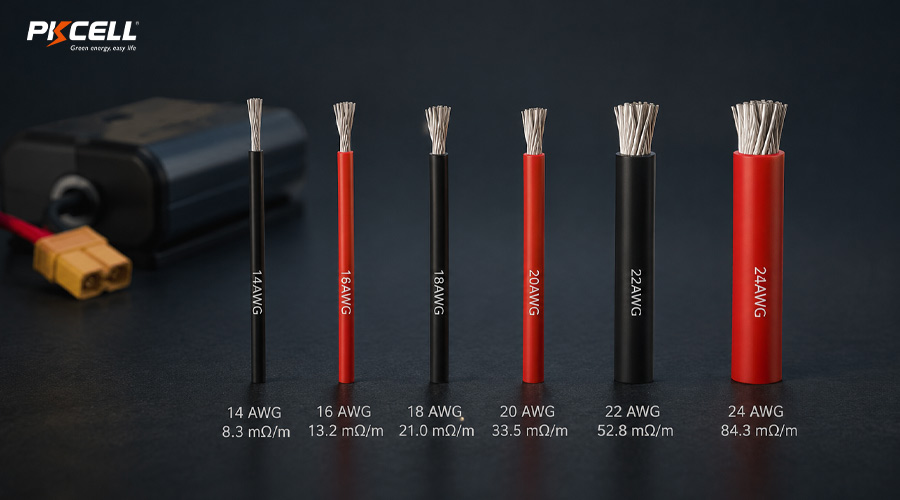
| Wire gauge | Reference resistance per meter | Relative voltage drop | Typical design implication |
|---|---|---|---|
| 14 AWG | 8.3 mΩ/m | Lower | More copper area, but greater diameter and reduced routing flexibility |
| 16 AWG | 13.2 mΩ/m | Low | Useful candidate when 18 AWG loss is too high and the connector accepts 16 AWG |
| 18 AWG | 21.0 mΩ/m | Moderate | Common comparison point for compact power wiring |
| 20 AWG | 33.5 mΩ/m | Higher | Smaller cable, but voltage drop and heat rise faster at high current |
| 22 AWG | 52.8 mΩ/m | Much higher | May suit lower-current or short connections after thermal and drop checks |
| 24 AWG | 84.3 mΩ/m | Highest in this comparison | Often more appropriate for low-current circuits than main pack output |
Table note: These reference values are based on NI’s published wire-gauge comparison and are included for first-pass comparison only. Use the resistance specification for the exact production wire. The table is not an ampacity chart.
Worked Example: 12 V Pack, 8 A Load, 0.6 m Cable
Design inputs
Assume a 12 V-class battery pack supplies an 8 A continuous load. The one-way cable distance is 0.6 m, so the positive and negative wires create a 1.2 m loop. Connector, BMS, and terminal losses are excluded from this simplified wire-only comparison.
20 AWG: 33.5 mΩ/m × 1.2 m = 40.2 mΩ
Voltage drop = 8 A × 0.0402 Ω = 0.322 V
Wire loss = 8² × 0.0402 Ω = 2.57 W
18 AWG: 21.0 mΩ/m × 1.2 m = 25.2 mΩ
Voltage drop = 8 A × 0.0252 Ω = 0.202 V
Wire loss = 8² × 0.0252 Ω = 1.61 W
16 AWG: 13.2 mΩ/m × 1.2 m = 15.84 mΩ
Voltage drop = 8 A × 0.01584 Ω = 0.127 V
Wire loss = 8² × 0.01584 Ω = 1.01 W
This calculation does not automatically make 16 AWG the final choice. The engineer must still verify allowable temperature rise, insulation rating, connector and terminal compatibility, fuse coordination, bend radius, enclosure space, vibration, cost, and production capability. It does show why cable length cannot be separated from current and voltage-drop requirements.
Why an Ampacity Chart Is Not Enough
Ampacity depends on how the cable is used and tested. A single wire in free air can dissipate heat differently from multiple conductors bundled inside a sealed battery enclosure. The acceptable conductor temperature also depends on insulation rating, terminal materials, neighboring cells, ambient conditions, and product safety limits.
Evaluate at least the following:
- Maximum continuous current and duration
- Pulse current, repetition rate, and thermal recovery
- Maximum internal pack and ambient temperatures
- Number of current-carrying wires in a bundle
- Enclosure ventilation and proximity to hot cells or BMS components
- Wire insulation temperature rating
- Permitted temperature rise at conductors, terminals, and connectors
- Short-circuit protection and fuse clearing behavior
- Applicable product, wiring, and market requirements
Final validation should measure temperature at the wire, crimp barrel, connector contact, PCB termination, fuse, and BMS current path during the worst credible duty cycle. A cable that remains cool while a connector overheats is not an acceptable system.
The Connector and Terminal Can Be the Real Limit
A larger wire does not increase the rating of a connector contact. The connector family, contact plating, circuit count, temperature rise, housing, mating condition, and exact terminal all influence current capability. Molex product specifications, for example, tie ratings to wire gauge and defined temperature-rise test conditions rather than presenting one unlimited connector current.
The crimp terminal must also be designed for the chosen conductor size, strand construction, and insulation diameter. Putting an oversized conductor into an incompatible terminal can damage strands, prevent correct crimp geometry, increase insertion problems, or reduce retention. Using an undersized conductor in a large terminal can also produce an unreliable crimp.
- Match wire gauge and insulation diameter to the terminal specification.
- Use the specified applicator, crimp height, pull-force criteria, and inspection plan.
- Verify contact current with the actual number of loaded circuits.
- Include mating cycles, vibration, contamination, and temperature exposure where relevant.
- Add strain relief so cable motion is not transferred directly to the crimp.
PKCELL’s custom lithium-ion battery pack options support custom wire lengths and connector choices such as JST, Molex, and Hirose, subject to project requirements and engineering review.
Need help specifying battery wires and connectors?
Send PKCELL your pack voltage, continuous and peak current, pulse duration, cable length, connector preference, enclosure drawing, operating temperature, and target certifications. The engineering team can review the complete current path and prototype requirements.
Main Power Leads, Balance Leads, and Sensor Wires
Not every wire in a battery pack carries the same current or serves the same purpose.
- Main output leads: Carry charge and discharge current and usually dominate voltage-drop and heating calculations.
- Separate charge leads: May carry a different maximum current and require a different connector or fuse strategy.
- Balance and cell-sense leads: Carry low current but require correct routing, insulation, connector pinout, and protection against shorts.
- NTC sensor wires: Carry measurement signals and should be routed to avoid noise and mechanical damage.
- Communication wires: CAN, UART, SMBus, or other interfaces may need controlled routing, grounding, or twisted pairs.
Do not enlarge every wire simply because the main output needs a larger gauge. Assign each circuit a specification based on current, voltage, protection, signal integrity, mechanical risk, and assembly requirements.
Mechanical and Environmental Requirements
Electrical calculations can identify a minimum candidate, but the production wire must survive the product environment. Check:
- Flexibility and bend life: Especially important for removable packs, hinged devices, robotics, and service loops.
- Minimum bend radius: Tight routing can stress conductors, insulation, and connector exits.
- Abrasion and edge protection: Use appropriate sleeves, grommets, channels, and strain relief.
- Vibration and shock: Prevent wire movement from loading welds, solder joints, or crimps.
- Chemical and moisture exposure: Match insulation, seals, and terminals to the environment.
- Assembly tolerance: Define length and stripping tolerances so the harness fits without tension or excess loops.
- Serviceability: Avoid connector placement that invites reverse mating or damage during maintenance.
PKCELL’s custom battery pack service includes configurable wires, cables, connectors, terminations, pack structures, and protection options for application-specific integration.
A Practical Battery Pack Wire Selection Workflow
- Define the electrical architecture. Record pack voltage range, charger path, discharge path, grounding, fuse, BMS, connector, and device cutoff.
- Capture the load profile. Include continuous, startup, stall, pulse, fault, and charging currents with durations.
- Measure the routed length. Calculate the complete positive and negative conductor path.
- Set a voltage-drop allocation. Reserve margin for cells, BMS, fuse, connectors, switches, and PCB traces.
- Screen candidate gauges. Use maximum specified conductor resistance rather than a nominal internet chart.
- Check temperature rise. Account for ambient temperature, insulation, bundling, duty cycle, enclosure, and nearby heat sources.
- Verify connector compatibility. Match the wire, terminal, seal, housing, current rating, and crimp process.
- Check mechanical integration. Confirm routing, bend radius, strain relief, grommets, abrasion protection, and assembly tolerance.
- Build production-intent prototypes. Use the intended wire, terminals, tooling, BMS, fuse, connector, enclosure, and cells.
- Validate worst cases. Measure voltage and temperature at low SOC, maximum load, maximum ambient, repeated pulses, and aged conditions.
- Lock the specification. Control conductor, gauge, stranding, plating, insulation, color, length, strip dimensions, terminals, crimp criteria, and approved suppliers.
OEM teams can also review PKCELL’s battery engineering workflow for consumer electronics, which covers requirements, cell selection, BMS and structural design, prototypes, testing, certification support, and mass production.
Common Wire-Gauge Selection Mistakes
- Using a generic ampacity number without its test conditions
- Calculating only the one-way cable length in a two-wire DC circuit
- Ignoring the percentage impact of voltage drop in low-voltage packs
- Sizing to average current while ignoring startup or repeated pulse loads
- Treating BMS overcurrent protection as the wire’s normal current rating
- Using nominal conductor resistance instead of the production maximum
- Ignoring resistance increase at elevated temperature
- Assuming the connector can carry whatever the wire can carry
- Using a wire outside the crimp terminal’s approved gauge range
- Forgetting fuse, MOSFET, weld, busbar, PCB, switch, and contact losses
- Validating an open cable instead of the assembled enclosed pack
- Changing wire or connector suppliers without requalification
What to Include in a Custom Battery Pack Inquiry
For a faster, more accurate wiring recommendation, provide:
- Battery chemistry, nominal voltage, maximum charge voltage, and capacity
- Continuous, peak, startup, and fault currents with durations
- Required positive and negative wire lengths
- Maximum acceptable device-side voltage drop
- Connector manufacturer, family, part number, and mating connector if specified
- Available cable diameter, routing space, and bend requirements
- Operating, charging, and storage temperatures
- Vibration, moisture, chemicals, flexing, or abrasion exposure
- BMS communication, NTC, balance, and separate charge-port requirements
- Prototype quantity, annual volume, target market, and certifications
Available cells and example pack configurations can be reviewed in PKCELL’s rechargeable battery product range.
Frequently Asked Questions
What wire gauge should I use for a battery pack?
There is no universal gauge for a given current. The correct choice depends on continuous and peak current, total loop length, voltage-drop budget, insulation rating, ambient temperature, bundling, connector, terminal, fuse, routing, and applicable standards. Calculate candidates and validate the complete assembly.
Should battery cable length be doubled for voltage-drop calculations?
For a typical two-wire DC circuit, include both the positive and negative conductor lengths. When they are equal, total loop length is twice the one-way distance. Use the actual architecture for chassis-return or other nonstandard circuits.
Is voltage drop more important than ampacity?
Both must pass. Thermal analysis prevents excessive conductor and connection temperatures, while voltage-drop analysis ensures the device receives adequate voltage. A cable may pass one requirement and fail the other.
Can I use a larger wire with the same battery connector?
Only if the exact terminal, seal, housing, and crimp process approve that conductor gauge and insulation diameter. The connector’s current and temperature-rise limits still apply even when the cable becomes larger.
Why does a battery cable get hot near the connector?
Localized heat may come from contact resistance, an incorrect or damaged crimp, contamination, partial mating, terminal wear, undersized conductors, excessive current, or poor strain relief. Inspect and test the entire connection rather than assuming the wire gauge is the only cause.
Conclusion: Select the Whole Current Path
Battery pack wire gauge should be selected from the load profile, complete conductor length, voltage-drop budget, and thermal environment. The final specification must also match the connector, crimp terminal, fuse, BMS, insulation, enclosure, and mechanical duty. Calculate with conservative production data, then verify voltage and temperature on a production-intent pack under the worst credible operating conditions.
Request a Custom Battery Pack Wiring Review
Share your voltage, capacity, load profile, wire length, connector, enclosure, temperature range, quantity, and certification requirements with PKCELL. Our team can help develop a custom pack with application-matched cells, wiring, protection, and connections.
Post time: Aug-06-2026


