
Battery Module vs Battery Pack: Key OEM Differences
The terms battery module and battery pack are often used interchangeably in quotations, drawings and product discussions. For an OEM project, however, the distinction affects system ownership, mechanical integration, BMS design, testing, serviceability, cost and supplier responsibility.
This guide explains the practical hierarchy from cell to module to pack, compares the two integration levels and shows what OEM buyers should define before requesting a custom battery solution.
Battery Module vs Battery Pack: The Short Answer
A battery module is an organized group of battery cells with electrical interconnections and a supporting mechanical structure. It may also include voltage and temperature sensing, but it is not always ready to power the final device by itself.
A battery pack is a more complete assembly designed to deliver power to a product or system. It may contain one or more modules, a pack-level BMS, protection devices, wiring, connectors, enclosure, thermal components and communication interfaces.
In compact products, manufacturers may connect cells directly into a finished pack without using a separately replaceable module. The terminology should therefore be defined in the project specification rather than assumed.
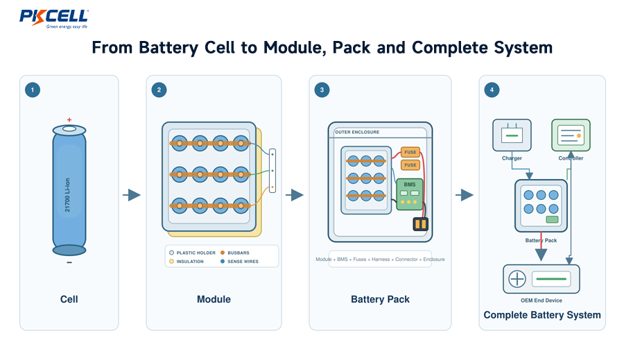
Understanding the Cell-to-System Hierarchy
This hierarchy is useful for communication, but not every project uses every layer. A wearable device might use one pouch cell with a small protection circuit. An industrial vehicle may use several modules inside a large pack with contactors, cooling and communication.
1. Battery Cell
A cell is the basic electrochemical unit. Examples include cylindrical 18650 and 21700 cells, lithium-polymer pouch cells, prismatic cells and NiMH cells.
Each cell has its own chemistry, nominal voltage, maximum charge voltage, capacity, current capability, internal resistance, temperature limits and cycle-life characteristics. PKCELL’s
rechargeable battery product range
provides examples of individual cells and assembled packs.
2. Cell Group
Cells can be connected in series, parallel or a combination of both. Series connections increase voltage, while parallel connections increase capacity and available current when the cells and electrical paths are properly matched.
For example, a 4S2P configuration contains eight cells: four series groups with two cells connected in parallel in each group.
3. Battery Module
A module combines multiple cells or cell groups into a mechanically organized subassembly. Common module components may include:
- Matched battery cells
- Cell holders, frames or compression structures
- Busbars, nickel strips or other interconnections
- Electrical insulation and barriers
- Voltage-sense wiring
- Temperature sensors
- Module terminals or connectors
- Module monitoring electronics in some architectures
- Cooling interfaces or heat-transfer components
A module is often designed as a repeatable building block. Several identical modules can be combined to create different pack voltages or energy levels.
4. Battery Pack
A battery pack is normally the assembly delivered as the power source for the OEM device. Depending on the project, it can include:
- One or more battery modules or a direct cell assembly
- Pack-level BMS or PCM
- Fuse or other current-interrupt protection
- Power wiring, busbars and output connectors
- NTC thermistors or other temperature sensors
- Balancing, fuel-gauge and communication functions
- Contactors and precharge circuitry for larger systems
- Mechanical enclosure, seals and mounting points
- Labels, identification and traceability information
- Thermal-management components
5. Complete Battery System
A complete battery system can extend beyond the pack to include the charger, power-distribution unit, DC-DC converter, cooling hardware, host controller, user interface and product-level safety controls.
Battery Module vs Battery Pack Comparison
| Comparison Point | Battery Module | Battery Pack |
|---|---|---|
| Primary purpose | Creates a repeatable electrical and mechanical building block | Provides an integrated power source for the final product |
| Typical contents | Cells, interconnections, support structure, insulation and sensing | Modules or cells, BMS, protection, harnesses, connectors, enclosure and interfaces |
| BMS | May have local monitoring or no independent BMS | Usually includes or interfaces with pack-level management and protection |
| Enclosure | May have an open frame or partial housing | Usually has a product-ready enclosure or defined outer wrapping |
| Output interface | Module terminals, busbars or internal connectors | Device-ready power, signal and communication connectors |
| Use by itself | Not always suitable as a standalone product power source | Normally intended to connect to and power the target device |
| Scalability | Can simplify families of packs using repeated modules | Usually optimized for one device, platform or voltage class |
| Service strategy | Can support module-level replacement when designed for it | May be serviced as one assembly or opened only by authorized personnel |
| OEM integration work | OEM may still own pack enclosure, BMS, high-current path and system validation | Supplier can deliver a more complete, application-specific assembly |
The most important difference is not the number of cells. It is the boundary between what the battery supplier delivers and what the OEM must still design, integrate and validate.
Why the Terminology Is Not Always Consistent
There is no single commercial naming convention used identically by every manufacturer and industry. One supplier may call a shrink-wrapped cell assembly a pack, while another reserves “pack” for a rigid enclosed assembly with a smart BMS and communication.
Similarly, a “module” could mean a simple framed cell group, a sealed subassembly with sensors or an intelligent unit with local monitoring electronics.
A clear interface-control document should state what is included, which company owns each design decision and what remains outside the supplier’s scope.
How Electrical Configuration Works at Each Level
Series and parallel notation describes electrical architecture, not whether an assembly is a module or pack.
- S value: Number of cell groups connected in series; determines voltage.
- P value: Number of cells connected in parallel per group; affects capacity and current capability.
- Module count: Number of mechanical or electrical subassemblies used in the pack.
Illustrative Architecture
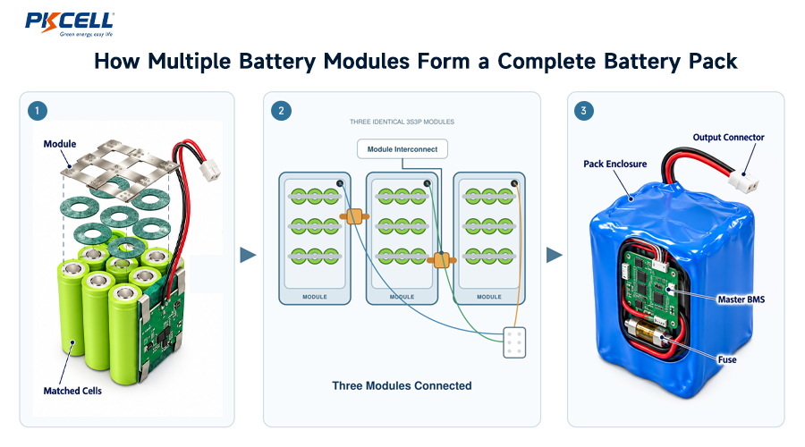
An OEM may create one module from a 4S2P cell arrangement. Three of those modules could then be connected in series inside the final pack.
- Cells per module: 4 × 2 = 8
- Modules per pack: 3
- Total cell count: 8 × 3 = 24
- Overall series structure: 12 series groups
- Overall parallel structure: 2 cells per group
The real design must also account for cell chemistry, voltage range, BMS channels, isolation, current paths, balancing, thermal behavior and fault response.
Cell consistency remains important at both module and pack level. Differences in voltage, capacity or resistance can cause unequal current sharing, premature cutoff or uneven heating. See PKCELL’s
battery cell matching guide
for the parameters that should be controlled during production.
Should an OEM Use a Battery Module or a Complete Pack?
A Battery Module May Fit When:
- The OEM already owns the pack enclosure and master BMS.
- Several product variants will use the same module.
- The system requires scalable voltage or capacity.
- The product has a defined module-replacement strategy.
- The OEM can validate module-to-module connections and pack-level faults.
- Mechanical and thermal integration are core OEM competencies.
A Complete Battery Pack May Fit When:
- The OEM wants one integrated battery assembly.
- Space, weight and connector position are tightly constrained.
- The supplier is expected to provide the BMS and enclosure.
- A device-ready harness and output interface are required.
- The project needs a consolidated prototype and validation path.
- The OEM prefers fewer battery-related integration responsibilities.
When Direct Cell-to-Pack Design Makes Sense
A small or medium battery pack does not always need a separate module layer. Cells can be integrated directly into the pack structure when this improves packaging efficiency, reduces interfaces or suits the production process.
Removing the separate module layer can reduce parts, connectors and unused structural volume. The tradeoff is that the design may be less modular and more difficult to service or adapt to a second product.
PKCELL’s guide to
custom battery pack design principles
discusses how cell count, interconnections, BMS location and pack architecture influence reliability and efficiency.
Seven OEM Design Differences That Matter
1. System Responsibility
Buying a module usually leaves more design responsibility with the OEM. The final pack may still require a master BMS, fusing, contactors, enclosure, connectors, charger coordination and product-level validation.
Buying a complete pack can shift more of this work to the battery supplier, but the OEM still owns integration with the device and the safety of the finished product.
2. BMS Architecture
A module may have no electronics, passive sensing or an intelligent monitoring board. A complete pack may need centralized or distributed BMS architecture, cell balancing, overvoltage and undervoltage protection, overcurrent response, temperature monitoring, state-of-charge estimation and communication.
PKCELL’s
OEM lithium-ion battery pack capabilities
include application-specific BMS functions, protection parameters and communication options.
3. Mechanical Integration
A module needs defined mounting points, compression requirements, tolerances and access for connections. A finished pack must also fit the host enclosure, survive product-level vibration and shock, provide strain relief and prevent damage to cells or insulation.
4. Thermal Management
Heat is generated in cells, interconnections, connectors and BMS power components. A modular architecture can make thermal paths repeatable, but interfaces between modules may create temperature differences.
The design should identify the hottest cells, coldest charging locations and heat produced by the electronics. Temperature sensors must be placed where they can represent the conditions being protected.
5. Connectors and Current Paths
Every module-to-module interface adds resistance, assembly steps and potential failure points. Connector current ratings should be checked against continuous load, pulse current, temperature, contact resistance, wire size and enclosure conditions.
For additional interface guidance, see
how to select a battery connector for an OEM device.
6. Serviceability
Replaceable modules can reduce the portion of a large pack that must be removed during service. However, replacement creates new requirements for state-of-charge matching, approved parts, access control, diagnostics and technician procedures.
A module should not be described as field-replaceable unless the electrical, mechanical and software architecture was designed and validated for that use.
7. Testing and Compliance Scope
Testing a cell or module does not automatically qualify every pack built from it. The exact pack configuration, electronics, enclosure, wiring and target market affect the required evaluation.
Transport documents, battery safety standards and finished-product requirements should be identified at the beginning of the project. Exact certification coverage must be confirmed for the selected design rather than inferred from a related cell or product family.
Common OEM Procurement Mistakes
Assuming a Module Is Ready to Power the Product
A module may lack a complete BMS, output connector, fuse, enclosure or user-safe interface. Confirm exactly what additional hardware is needed.
Specifying Only Voltage and Capacity
Two assemblies with the same voltage and amp-hour rating can have very different current capability, dimensions, thermal behavior, service life and protection functions.
Leaving the BMS Ownership Undefined
The quotation should state who designs the BMS, supplies firmware, defines thresholds, verifies programming and controls future component or software changes.
Ignoring Module-to-Module Variation
A pack containing several modules must account for capacity, state-of-charge, resistance and temperature differences between modules as well as differences between individual cells.
Designing the Enclosure Before Confirming Pack Details
The mechanical envelope should include cell tolerances, holders, insulation, BMS, wires, connector clearance, mounting features and possible thermal interfaces.
Treating Certification as a Supplier Logo
Ask which exact cell, module or pack configuration is covered, which report is available and whether the planned modification changes the assessment.
Skipping Production Change Control
Cell substitutions, BMS component changes, firmware revisions, connector alternatives and enclosure-material changes can affect performance or compliance. Define approval rules before mass production.
What to Include in a Battery Module or Pack RFQ
- Application and device operating description
- Required integration level: cell group, module or complete pack
- Cell chemistry and preferred cell format
- Nominal, minimum and maximum system voltage
- Required capacity, energy and runtime
- Series-parallel configuration, if already defined
- Continuous, peak, startup and charging currents
- Pulse duration, repetition and duty cycle
- Maximum dimensions, weight and mounting orientation
- Operating, charging and storage temperatures
- Cooling method and enclosure conditions
- BMS protection, balancing and fuel-gauge requirements
- Communication protocol and host-system interface
- Connector, pinout, wire gauge and cable length
- Charger or charging-interface requirements
- Service and replacement strategy
- Target markets and required compliance documents
- Prototype quantity, annual forecast and launch schedule
Providing this information helps the supplier determine whether a module, direct cell-to-pack design or finished custom pack is the most practical architecture.
Discuss Your OEM Battery Architecture
Share your voltage, capacity, load profile, available space, BMS requirements, connector, operating environment and production forecast. PKCELL can review whether your project needs a battery module, a complete pack or a direct cell-to-pack solution.
Request an OEM Battery Quote
Explore Custom Battery Services
Frequently Asked Questions
Is a battery module the same as a battery pack?
Not usually. A module is commonly a cell-based subassembly intended for integration into a larger pack. A pack is normally the more complete power assembly connected to the product. Because suppliers use these terms differently, the included components and interfaces should always be defined.
Can a battery pack contain only one module?
Yes. A pack can use one module, several modules or no separately defined module layer. Its architecture depends on voltage, energy, size, serviceability and manufacturing requirements.
Does every battery module have a BMS?
No. A module may contain only cells, interconnections and sensors. Other modules include local monitoring electronics. The complete pack may still require a master BMS and pack-level protection.
Can an OEM connect battery modules in series?
Modules can be designed for series connection, but their voltage ratings, insulation, sensing, balancing, connectors and BMS architecture must support the complete string. Modules should not be placed in series merely because their individual voltages appear compatible.
Is a modular battery always easier to repair?
Not automatically. Safe module replacement requires physical access, compatible replacement parts, diagnostics, isolation procedures and rules for voltage and state-of-charge matching.
Which is less expensive: a battery module or a battery pack?
A module may have a lower purchase price because it includes fewer system components, but the OEM must account for the remaining BMS, enclosure, wiring, assembly, testing and validation work. Total system cost is more useful than unit price alone.
Can PKCELL customize both modules and complete battery packs?
PKCELL supports application-specific cell selection, series-parallel configuration, BMS or PCM, wiring, connectors, casing and pack structure subject to engineering review. The final supply boundary should be agreed during quotation and prototype development.
Conclusion
In a typical OEM architecture, a battery module organizes cells into a repeatable electrical and mechanical unit, while a battery pack combines the required cells or modules with management, protection, connections and packaging for the final application.
The terminology alone is not enough to define a deliverable. OEM teams should document the cell configuration, BMS responsibility, enclosure, connectors, thermal design, communication, testing scope and system interfaces.
A well-defined supply boundary prevents missing components, duplicated engineering and late-stage integration problems. Submit your project parameters through the
PKCELL battery inquiry form
for an application-specific module or battery pack proposal.
Post time: Sep-18-2026


