
18650 Battery Packs for Cordless Tire Inflators: What OEMs Should Evaluate Before Sourcing
A cordless tire inflator looks like a straightforward motorized product, but its battery requirement is more demanding than its average wattage suggests. The compressor must start reliably, continue working as tire pressure rises, tolerate repeated inflation cycles, and avoid nuisance shutdown when the battery is warm or partly discharged.
For OEM teams, selecting an 18650 battery pack for a cordless tire inflator therefore requires more than comparing voltage, capacity, and price. The pack must be engineered around the complete inflation event, including motor startup, rising back pressure, voltage sag, protection timing, heat accumulation, and the performance promised to the end user.
Why Tire Inflators Need an Application-Specific Battery Specification
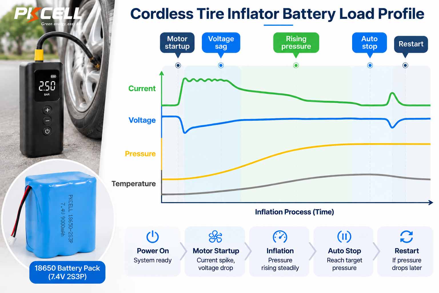
A tire inflator does not present one constant load. Its compressor, motor controller, display, pressure sensor, work light, cooling fan, and USB functions may all draw power differently. More importantly, compressor demand changes throughout the inflation process.
A battery specification based only on a motor label or nominal product wattage can miss the conditions that cause field failures. An inflator may run normally at full charge yet stop early when the battery is partly discharged. It may inflate one tire successfully but overheat during the second or third. A pack may also pass a room-temperature bench test while producing an unacceptable startup dip after being stored in a cold vehicle.
A useful tire inflator specification describes an operating event, not merely a current rating.
Break the inflation event into measurable phases
| Operating phase | Battery behavior to measure | Why it matters |
|---|---|---|
| Power-on and electronics startup | Inrush current, controller boot voltage, standby consumption | A voltage dip can reset the display or controller before the compressor starts. |
| Motor startup | Peak current, pulse width, minimum pack voltage, BMS response | The BMS must pass normal startup without confusing it with a fault. |
| Low-pressure inflation | Running current, airflow, pack voltage, temperature rise | This establishes the early operating load and baseline efficiency. |
| Rising-pressure operation | Current versus pressure, speed variation, voltage sag | Motor demand and heat can change as the tire approaches its target pressure. |
| Automatic stop and restart | Control accuracy, restart peak, BMS recovery behavior | Top-off cycles can create repeated peaks with little cooling time. |
| Blocked hose or motor stall | Fault current, shutdown delay, fuse and BMS response | Normal inflation must be separated from a credible abnormal condition. |
1. Start with the Full Battery Voltage Window
Nominal voltage is only a label. An 18650 lithium-ion pack operates across a voltage range, and both ends of that range influence inflator performance. The OEM should define the pack voltage at full charge, during normal operation, at the product’s low-battery warning, and at final shutdown.
The selected series configuration must be compatible with the motor, controller, charger, display electronics, and protection circuit across that entire window. A motor designed around one voltage architecture should not be assigned a different series count merely to improve a headline specification.
At the lower end of the discharge curve, a regulated or approximately constant-power system may draw more current to maintain output. That makes low-state-of-charge testing particularly important.
As pack voltage falls, current may rise. Higher current then causes additional voltage drop and resistive heating, potentially creating a feedback loop that leads to early shutdown.
2. Evaluate Voltage Sag, Not Open-Circuit Voltage Alone
A pack can show a normal voltage with the compressor off and still fall below the controller or BMS threshold when the motor starts. This difference between resting voltage and loaded voltage is central to tire inflator performance.
Total resistance includes the cells, welded interconnects, BMS MOSFETs, PCB conductors, fuse, wiring, connector, and device-side contacts. Cell resistance also tends to vary with temperature, state of charge, manufacturing variation, and aging.
OEMs should request voltage-versus-time plots rather than a simple “pass” result. At minimum, the plots should show the lowest pack voltage during startup, voltage recovery after startup, voltage during high-pressure operation, and individual series-group behavior where practical.
3. Choose 18650 Cells by Usable Power and Energy
The highest-capacity 18650 cell is not automatically the best choice for a cordless compressor. Capacity supports runtime, while internal resistance, verified discharge capability, and thermal behavior influence whether that capacity can be used under the actual load.
A practical screening process should compare:
- Exact cell manufacturer and model, not only the “18650” format name;
- Nominal and minimum capacity under a defined test method;
- Continuous-current capability under specified thermal conditions;
- Defined pulse performance, including pulse duration and rest time;
- DC internal resistance and voltage sag at relevant states of charge;
- Charge and discharge temperature limits;
- Performance after aging and resistance growth;
- Production-lot consistency and cell-matching controls;
- Long-term availability and change-notification expectations.
PKCELL’s guide to low-drain and high-drain 18650 batteries provides additional context on separating capacity, continuous current, and defined pulse capability. Current cell options can also be reviewed in the PKCELL 18650 battery range.
Do not multiply a cell rating without considering the pack
Adding cells in parallel can increase energy and distribute current, but current sharing is not perfectly equal. Differences in cell impedance, temperature, weld resistance, and conductor geometry can cause one branch to work harder than another.
The theoretical calculation below is a useful starting point, not a finished design rule:
The completed pack still needs validation for current imbalance, hot spots, low-state-of-charge behavior, and aged-cell performance.
4. Coordinate BMS Protection with Motor Behavior
A BMS current label does not fully describe how it will behave in an inflator. OEMs should distinguish normal continuous current, repetitive operating peaks, motor startup, overcurrent detection, short-circuit protection, and motor-stall current.
The protection system should allow normal startup and pressure-related load changes while responding appropriately to abnormal events. Parameters to document include:
- Continuous discharge-current limit under the pack’s thermal conditions;
- Permitted peak current, peak duration, and repetition;
- Overcurrent threshold, tolerance, and detection delay;
- Short-circuit detection and recovery method;
- Cell undervoltage thresholds and release behavior;
- Charge and discharge temperature protection;
- Series-group monitoring and balancing strategy;
- Fuse or secondary protection coordination;
- BMS hardware, firmware, and programmed-parameter revision.
For projects requiring application-specific protection, wiring, sensors, and pack construction, review PKCELL’s customized battery pack engineering service.
5. Test the Combined Heat from the Compressor and Battery
The battery is not the only heat source inside a cordless inflator. The motor, compressor head, controller, and internal wiring can warm the enclosure. Their heat may reach the pack even when the pack’s own electrical losses appear acceptable.
Thermal validation should replicate the intended use pattern, including consecutive tires, high target pressure, warm ambient conditions, restricted ventilation, and short intervals between inflation cycles. Temperature should be measured at the cells, BMS MOSFETs, welds, conductors, connector, and relevant enclosure surfaces.
Sensor placement deserves special attention. An NTC records the temperature at its mounting point; it does not automatically capture the hottest cell or the warmest BMS component. Thermal mapping should be used to identify the monitoring location that best represents the design risk.
Include charging after inflation
Users may connect the charger immediately after finishing a tire. The validation plan should therefore evaluate whether charging is permitted while the pack or compressor compartment remains warm. Any charge delay, temperature lockout, or user indication should be defined at the product level.
6. Review Every Part of the High-Current Path
A capable cell cannot compensate for excessive resistance elsewhere in the pack. At inflator operating current, undersized conductors or inconsistent connections can cause both voltage loss and concentrated heating.
The sourcing review should cover cell tabs, nickel or copper conductors, weld patterns, BMS PCB copper, MOSFETs, fuse elements, cable size, crimping, solder joints, and mating connectors. Mechanical drawings should define conductor dimensions and critical assembly processes rather than leaving these details to an uncontrolled substitution.
For additional production guidance, see how to validate spot-weld quality in 18650 and 21700 packs.
7. Translate “Tires per Charge” into a Repeatable Test
“Tires per charge” can be a valuable customer-facing claim, but it is meaningless without defined conditions. Tire volume, starting pressure, target pressure, leakage, hose restrictions, ambient temperature, battery age, and rest time can all affect the result.
OEM teams should define an internal reference test that records:
- Tire or calibrated test-volume specification;
- Starting and target pressure;
- Ambient and initial battery temperature;
- Initial battery state of charge;
- Inflation time and rest interval;
- Energy consumed per inflation event;
- Maximum cell, BMS, connector, and enclosure temperature;
- Automatic-stop accuracy and restart behavior;
- End-of-test voltage and shutdown reason.
Repeat the evaluation using production-intent samples, partly discharged packs, temperature limits, and aged cells. This gives marketing, engineering, and customer-support teams one controlled basis for product claims.
8. Mechanical Integration Matters in Vehicle and Workshop Use
A portable inflator may be carried in a vehicle, dropped into a toolbox, exposed to road vibration, or stored for long periods between uses. The pack structure must restrain the cells and electronics without creating damaging compression, abrasion, or sharp contact points.
Review the complete mechanical interface:
- Cell holders, cushioning, insulation, and clearances;
- Pack movement during drop and vibration events;
- Wire routing near the motor and compressor mechanism;
- Connector retention and cable strain relief;
- Protection from screws, ribs, and sharp enclosure features;
- Airflow paths and separation from hot components;
- Serviceability and prevention of incorrect replacement;
- Label location, serial identification, and traceability.
Flexible configurations can be explored in PKCELL’s 18650 battery pack portfolio, but final suitability must be confirmed against the inflator’s actual electrical and mechanical requirements.
9. Build a Validation Matrix Before Approving the Supplier
A sample that powers one prototype is not enough evidence for a production award. The validation plan should progress from engineering feasibility to production-process control.
| Stage | Primary purpose | Recommended evidence |
|---|---|---|
| Engineering validation | Confirm cell, configuration, current path, BMS concept, charger, and mechanical fit. | Load captures, voltage-sag plots, thermal maps, protection tests, drawings, and prototype results. |
| Design validation | Verify the integrated inflator across expected and abnormal operating conditions. | Repeated inflation, temperature limits, low SOC, stall response, drop, vibration, charging, and aging results. |
| Production validation | Demonstrate that the intended factory process can reproduce the approved pack. | Pilot-lot records, cell-lot traceability, process parameters, end-of-line tests, capability data, and defect actions. |
| Bulk-order release | Confirm configuration, documentation, capacity, packaging, and unresolved issues before shipment. | Approved BOM, inspection report, compliance documents, change control, packaging approval, and retained samples. |
PKCELL’s article on battery pack quality inspection before bulk orders explains how engineering samples, production-intent pilot builds, evidence packages, and release gates can be incorporated into purchasing controls.
10. Ask Suppliers for Evidence, Not Just Datasheet Values
A sourcing decision becomes more reliable when each important claim is linked to a test method, configuration revision, and production record. Before nomination, ask the battery supplier to provide or define:
- Exact cell make and model;
- Approved cell alternatives, if any;
- Pack drawing and controlled BOM;
- Series-parallel configuration;
- Cell-matching criteria and method;
- BMS schematic or functional specification;
- Protection thresholds and timing;
- Wire, connector, fuse, and conductor details;
- Capacity and load-test conditions;
- Voltage-sag and thermal-test data;
- Critical assembly process controls;
- Lot and component traceability;
- End-of-line test coverage;
- Change-notification procedure;
- Warranty and failure-analysis process;
- Lead time, MOQ, and forecast expectations.
Certificates and transport documentation should also be checked for the exact battery configuration and destination market. They should not be treated as substitutes for application validation or production-lot inspection. PKCELL publishes relevant company and product documentation on its battery certificates page.
11. Information to Include in an OEM RFQ
A well-prepared request for quotation helps the supplier evaluate the design rather than simply propose the closest catalog pack. Include the following information:
- Inflator model, intended user, and target markets;
- Nominal, full-charge, warning, and shutdown voltage;
- Measured startup, running, high-pressure, restart, and stall current;
- Pulse duration, repetition, inflation time, and rest time;
- Target tire-per-charge or energy-per-cycle requirement;
- Maximum battery dimensions, weight, and mounting constraints;
- Charging method, charge time, and adapter specification;
- Operating, storage, and charging temperature range;
- Connector, wire length, polarity, NTC, and communication requirements;
- Drop, vibration, ingress, and vehicle-storage expectations;
- Required compliance markets and documentation;
- Prototype quantity, annual forecast, launch date, and delivery region.
Request an 18650 Tire Inflator Battery Review
Send PKCELL your measured load profile, voltage window, battery-space drawing, runtime target, charger information, temperature range, annual forecast, and destination markets. The engineering team can review cell selection, series-parallel configuration, BMS settings, current-path design, samples, and production requirements.
Frequently Asked Questions
Are high-capacity 18650 cells suitable for every cordless tire inflator?
No. High capacity can improve available energy, but the exact cell must also support the inflator’s startup current, sustained pressure-related load, voltage-sag limit, and thermal conditions. A lower-capacity cell with more suitable power characteristics may perform better in a demanding design.
Why does a cordless inflator stop even though the battery indicator is not empty?
Possible causes include voltage sag under load, BMS overcurrent protection, an undersized conductor or connector, excessive temperature, an inaccurate state-of-charge estimate, or a controller cutoff that is reached during a current peak.
Should OEMs specify continuous current or peak current?
Both are needed, together with peak duration, repetition, rest time, temperature, state of charge, and allowable voltage drop. Startup current, high-pressure running current, and motor-stall current should be identified separately.
How should an OEM verify a tires-per-charge claim?
Use a documented test with a defined tire or test volume, starting pressure, target pressure, ambient temperature, initial battery condition, rest intervals, and shutdown criteria. Repeat the test at low temperature, low state of charge, and after battery aging where relevant.
Can an existing 18650 battery pack be used without customization?
Only if its voltage window, current capability, BMS behavior, connector, charger, dimensions, thermal performance, and mechanical construction match the inflator. Many OEM projects require customized wiring, protection settings, sensing, structure, or labeling even when standard 18650 cells are used.
Conclusion
Sourcing an 18650 battery pack for a cordless tire inflator is a system-engineering decision. The pack must start the compressor, tolerate rising load, limit voltage sag, manage accumulated heat, and continue meeting the product promise as the battery ages.
The strongest sourcing programs begin with measured inflator data, define the complete voltage and current envelope, validate realistic consecutive-use cycles, and connect every approved value to controlled production evidence. This approach helps OEMs reduce premature shutdowns, overheating complaints, inconsistent runtime, and late-stage redesigns before mass production begins.
Post time: Nov-16-2026


